
A few words for the introduction
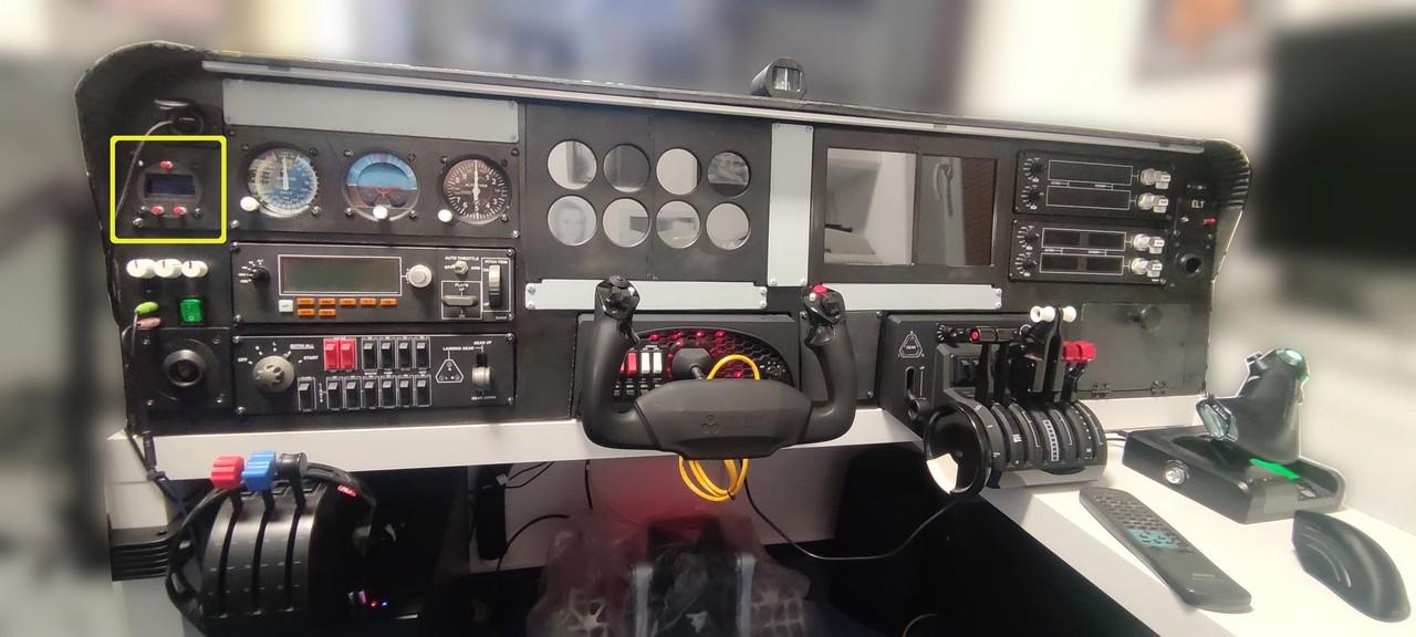
I write the clock, but this device shows a little more. In addition to the clock and stopwatch, it also displays voltage and temperature. Of course, this information comes from the simulator. This was the first device I printed on my 3D printer because it was the easiest to connect as well. And I had already played with the two-line display in Arduino a few days before. Of course, if it weren’t of Captain Bob’s videos, walkthroughs, and complete MobiFlight programming, I would have struggled with this for much longer.
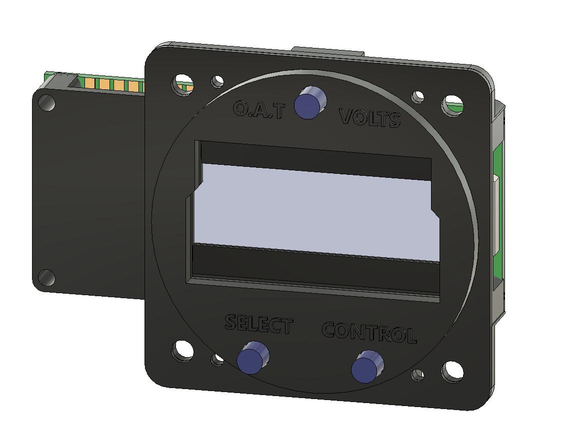
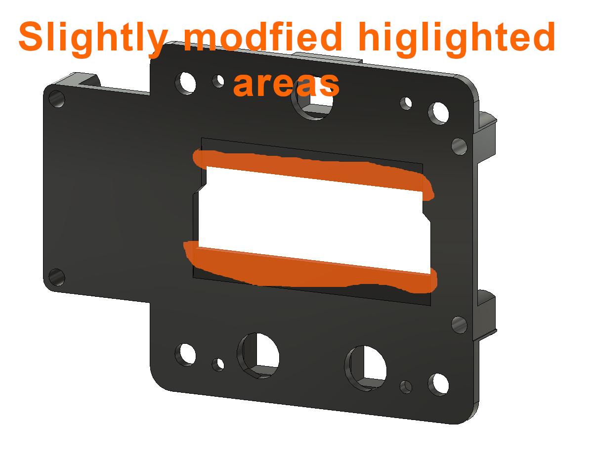
Nevertheless, this first device pushed me to take the first few steps with Autodesk Fusion, so that I could modify the 3D model a little to my liking. I slightly adjusted the opening through which the two-line display can be seen, so that its edges are not visible and the whole device looks more … “uniform”? I don’t know how to describe it more accurately. Below you will find links to Captain Bob’s original video on how to assemble the instrument, as well as his and my modified version.
Gallery
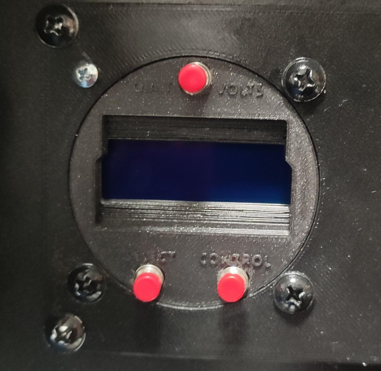
The description is a good thing, but the picture is just fine:
Wiring
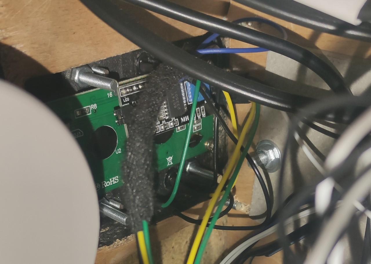
Below is a picture of the clock wiring, well, as I have it:
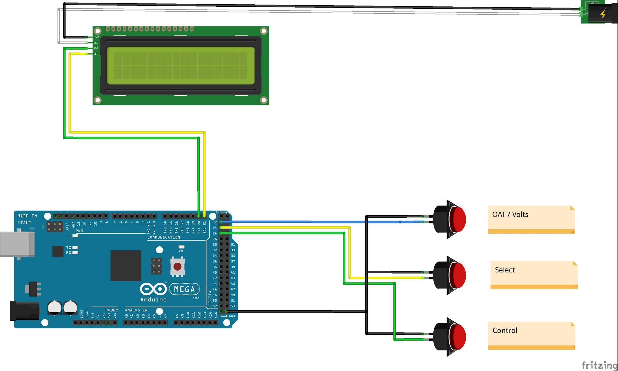
Despite the fact that this device uses a rather complex component, such as a 2-line display, its wiring is simple. The display requires power, these are the white (+5V) and black cable (-). The display I used uses the I2C bus for communication and it also only requires two cables. These are yellow (SCL) and green (SDA). Here, it will have to be enough for you that these two cables are enough for the display. If you want to learn more about what each of the two does, you’ll need to delve into the Arduino documentation.
Then the clock contains only 3 buttons, each containing 2 pins. We will connect one of them to the Arduino input (colored cables) so that the button press can be detected. Well, with second cable, we will close the circuit, how else, than by connecting it to the GND pin (black cable), i.e. to the ground.
You can also notice in the wiring diagram the connection of the GND pin from the Arduino to the negative pole (so also GND) of the external power supply. Connecting the GND pins of all circuits is important to create a common reference point, which allows for proper communication and functioning of all devices. Without a common ground, signals can be misinterpreted, leading to incorrect operation. Proper grounding also reduces electrical noise and improves the stability and safety of circuits. In practice, I solved this by connecting the GND output from the PC power supply to the GND pin on the Arduino. It is described in Chapter 2 – Switches, dials and similar.
Downloads
Below you can download an archive of my modified DAVTRON clock files:
And the files to print the instrument panel:
MobiFlight programming of the whole cockpit:
Links
Let’s start with the links to resources from from Captain Bob….
- Video-tutorial to assemble the clock from Captain Bob
- Captain’s Bob Website
- Captain’s Bob Cessna 172 project on Github
- Captain’s Bob source files for the SMALL_OAT Clock Davtron 803 on Github
And some links to used parts:
- Arduino Mega2560
- 16×2 blue LCD display 1602 I2C for Arduino (they are usually part of various Arduino starter kits)
And used software:
All episodes of the series:
- My “home” cockpit
- Switches, dials and similar
- Instrument panel – DAVTRON Clock – this one 🙂
- Instrument panel – Airspeed indicator
- Instrument panel – Attitude indicator
- Instrument panel – Altimeter
- PFD & MFD
- ELT Panel
- Compass
- Ventilation system
- Conclusion of the first phase, summary, and thanks
Changes in this article
12.11.2024 – Added a paragraph about connecting the Arduino GND pin to an external power supply to create a common ground between all components (which is quite important and I didn’t have it there) to the Wiring chapter. The wiring diagram was also updated.