

A few words for the introduction
Originally, I didn’t think about sharing this “panel”. As for this panel, I again did not start on the “green field”. I’m always trying to modify as least as possible, in the project that I build upon on. Maybe it has something to do with laziness. I just wanted to build a simple panel – the freely available Honeycomb Bravo Quadrant B737 Add-On. But due to the way my sim cockpit is arranged, I ended up designing a whole new panel of my own, using just the “handles” from the mentioned project. So, maybe, just for the minor probability of somebody else finding it useful, here I share…
Gallery
A description is a good thing, but pictures are better:
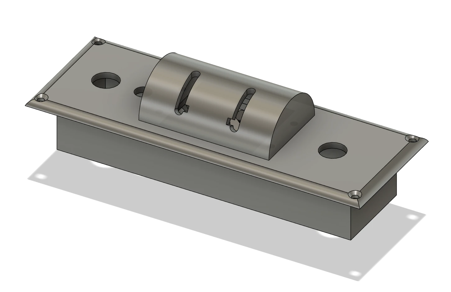
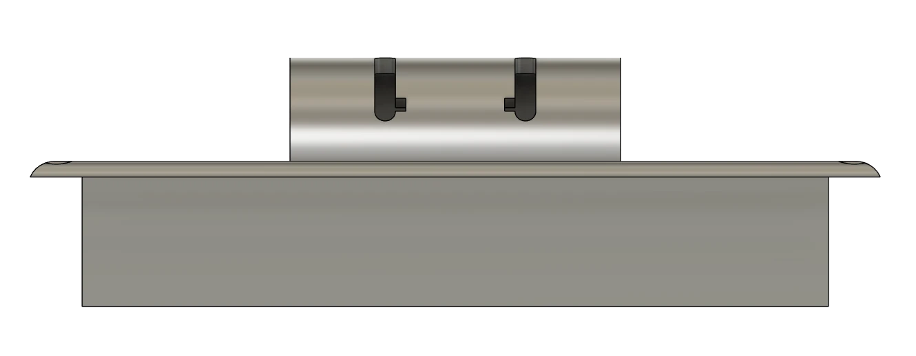
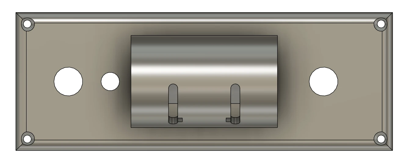
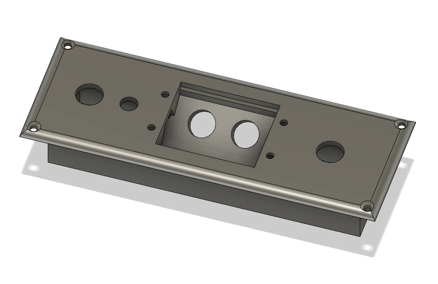

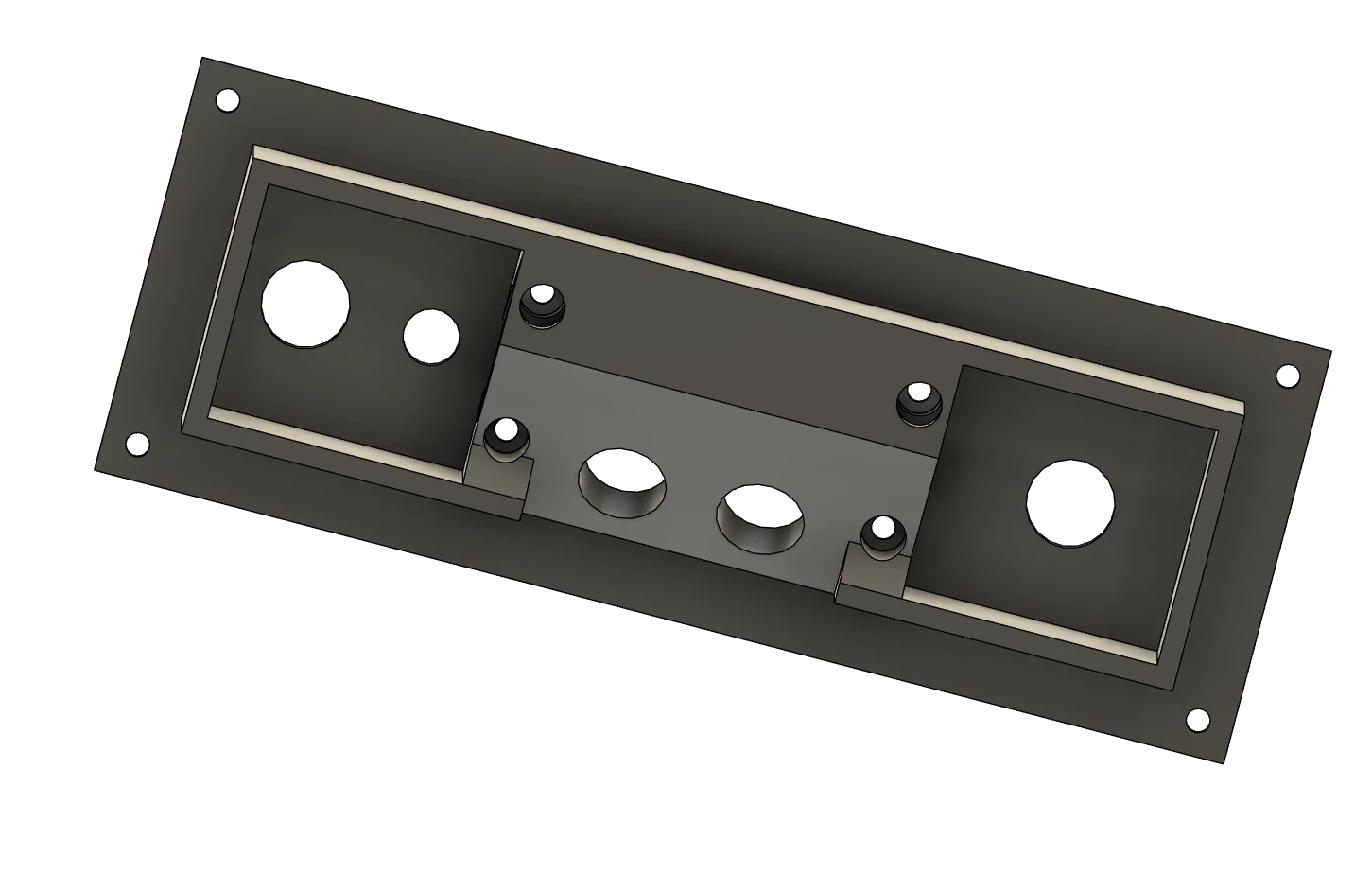
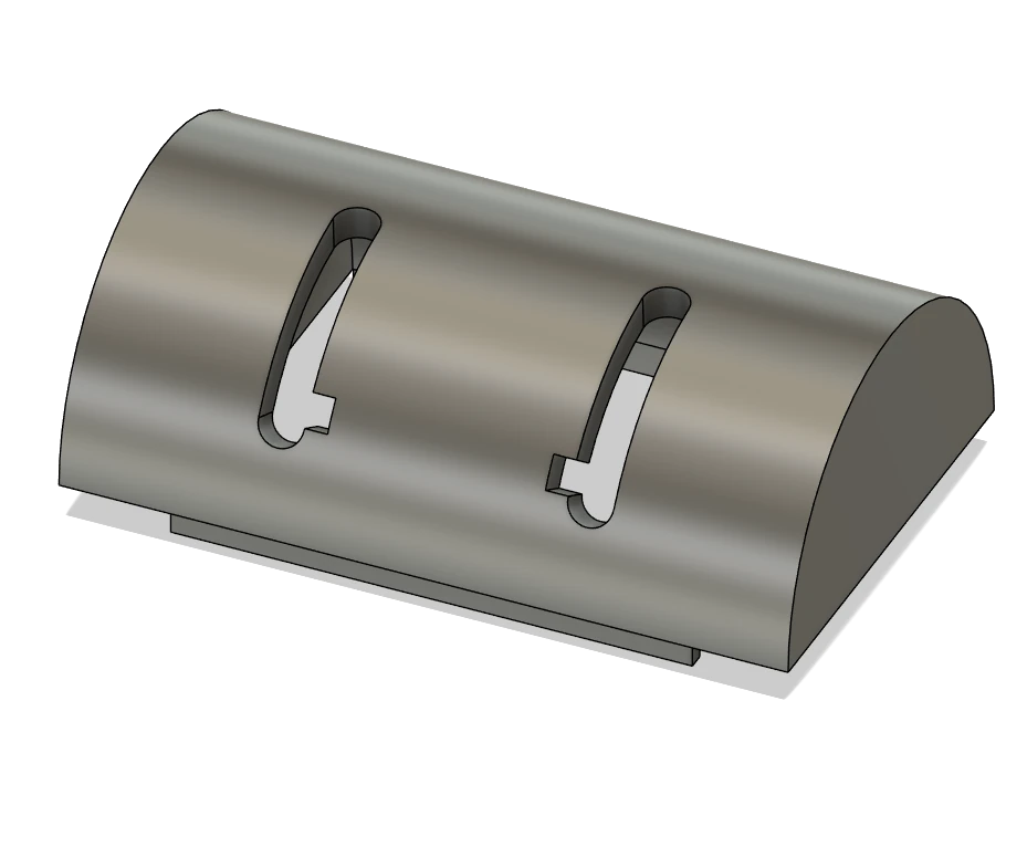
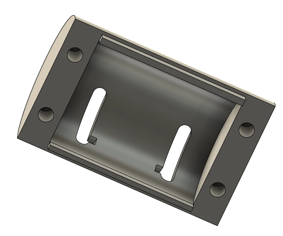
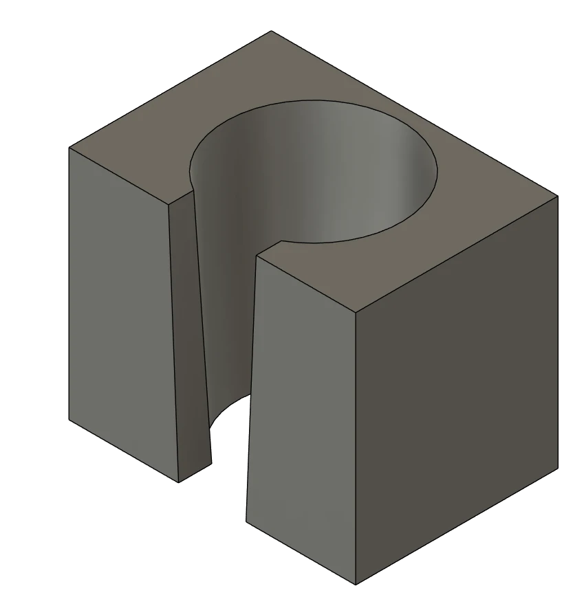
The panel is relatively small. Each “section” is approximately 4×4 cm (1.5 x 1.5 inches). On the left, there will be toggle switch for parking brake and LED light signaling whether the parking brake is on or off. In the middle “dome” section, there will be hidden two engine start switches and in the right “section” – the one with one hole, there will be push button for landing gear warning HORN CUTOUT.
So, the functionality is the same as in Honeycomb Bravo Quadrant B737 Add-On. The panel is divided into a “body” and a “engine start switches cover”. This is done intentionally for easier printing … and … also, if it were one piece, later, when you would want to mount those switches, you might find it to be a more advanced magic trick 🙂
The engine switches cover has 4 holes on the bottom, where 4 threaded inserts in plastic for M3 screws should go. The cover is then screwed to the body from the bottom.
Wiring
Below is a picture of the panel wiring:

From the wiring perspective, this panel is very easy. It has 3 switches, 1 button and 1 LED, so we can use the same “approach” as we did with ELT panel, just with more switches.
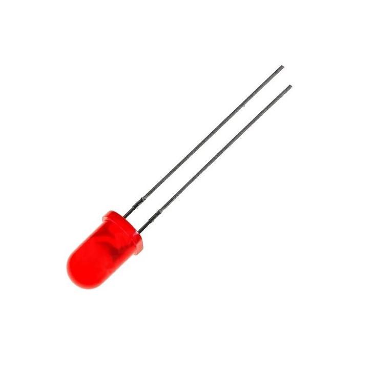
At the wiring diagram above, you can see that each component has one leg (input) connected to ground (GROUND) and the other to some Arduino input/output. The LED has cathode connected to ground and anode (the longer or slightly curved leg) to Arduino via 330Ω resistor (to make sure there is always safe current to it).
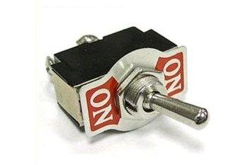
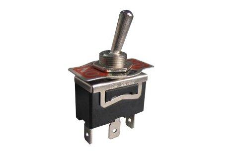
The three toggle switches have the middle leg (leg 1) connected to ground (GROUND) and leg number 3 to Arduino input’s. I used type KN3(C)-102AP toggle switches, which are ON-ON type, but ON-OFF types can be used as well. Because we need toggle switches here, we only care to know one state, either ON or OFF. If its not in ON, we know it must be OFF. To use leg 3 for Arduino input’s was just my choice, you can use leg 2, if you want.
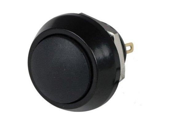
The connection of wires on the PBS-33B push button is as you grab it while soldering, it does not matter – as long as one leg is connected to ground and the other to Arduino.
You may notice that the ground wires have brown and brown-white color, instead of black as in my other wirings …) That is because I used an ethernet cable for this panel. The paired brown and brown-white wires I used for common ground connection then.
I also did not want to hard-wire the components with the connecting ethernet wire – for the sake of repairs and maintenance. So I crimped a “mid-connector” between the panel components and the wire connecting it all to Arduino. 5 PINs are for “signal” cables and one is for “ground” wires. The one for ground wires is connected to “reduction” that combines the five ground wires to single pin (that brown – brown-white pair in the ethernet cable). You can see that at the photos:


Below is a gallery with used parts… hopefully they will help you find alternatives, when in a few months the links below will no longer be valid 🙁
Programming
As well as wiring, neither the programming should cause you sleepless nights, like college exams or waiting for the new episodes of your favorite TV show…
Input /Output definitions
First, you need to define the inputs. We have 4 buttons here and one LED output. For each of them, there is not much to setup except the PIN they sit on. And yours can be different 🙂 Than just give them some reasonable names. I defined mine as follows:

Starting at the selected line, EP is a short for Engine Panel, and I go:
| Name | Description | PIN |
|---|---|---|
| EP_HC_BTN | Horn Cutout Button | 53 |
| EP_LE_IGN_SW | Left Engine Start Switch | 51 |
| EP_RE_IGN_SW | Right Engine Start Switch | 49 |
| EP_PBRK_SW | Parking Brake Switch | 47 |
| EP_PBRK_LED | Parking Brake LED | 45 |
Programming Horn Cutout Button
For the Horn Cutout Button (Switch), and other switches too, we will use “PMDG events”. If that doesn’t ring any bell for you … it’s just a way how to trigger some action within PMDG aircraft, mostly to interact with some cockpit switch, button, lever etc. It is easy to setup, as MobiFlight just knows them all (I think). Most of them also require some parameter, which can mean a mouse press, release, drag… but in our case of buttons and switches, it will take as parameter value 1 or 0, where 1 usually means “pressed” and 0 means “release”. For more information, read the SDK documentation that is shipped with the PMDG 737-800.
So, to handle the Horn Cutout Button, create a new Input Config in MobiFlight, give it some meaningful name, like “EP – Hurn Cutout Button“, as I did, and click the button on the right with tree dots, or double-click the entry, to open the following config dialog:

Here at the Input section we need to choose our board that the Horn Cutout Button is connected to. That is the Module option. I set it to MF_Mega_CB. In the Device list, choose the PIN the Horn Cutout Button is connected to – EP_HC_BTN.
Next, in the Input Section, we will deal with the first tab – On Press. In the Action Type list, select FSUIPC – PMDG – Event ID. This should show or enable the following section – Load preset, in which you click on B737 (because we are setting it for Boeing 737) and in the list below, find EVT_CONTROL_STAND_HORN_CUTOUT_SWITCH. After you select it, click the Use button just to the right of the list. This will place number 70345 in the Event ID option below, in the Customize Settings section. In the Mouse Param option, the Custom Param value should be pre-selected. Change it if not. And then type 1 in the Custom Param option. This is it for the event when the button is pressed – it will send PMDG event which will tell the aircraft to press the Horn Cutout button, reflecting what we did in physical world.
Now switch to On Release tab. Set everything the same as for On Press, except the last Custom Param option. This time,set it to 0 – telling the aircraft to release the button.

Programming Engine Start Switches
Programming the engine start switches follows the very same approach as in the case of Horn Cutout Button. Just the short final and touchdown are different, indeed.
So, again, you need to create new Input config(s), name it, eg. EP – Left Engine Start Switch and set the On Press tab:
Module -> MF_Mega_CB
Device -> EP_LE_IGN_SW
Action Type -> FSUIPC – PMDG – Event ID
Load preset -> B737, EVT_CONTROL_STAND_ENG1_START_LEVER
Click Use
Event ID -> 70320 (filled by Use button)
Mouse Param -> Custom Param
Custom Param -> 1
just as on the following picture:

in the On Release, everything is the same again, except the:
Custom Param -> 0

The same way applies for the second engine start lever, except there you are looking for: EVT_CONTROL_STAND_ENG2_START_LEVER event.
Programming the Parking Brake Switch
The parking brake switch might be a little tricky and it depends on the option you have set for brakes in PMDG 737. You can have either Realistic or Simple. I have realistic, so I will show you the setup for that. I will also show the setup with generic parking brake control for any other aircraft that uses standard controls / events.
Using PMDG event with realistic brakes
When using realistic brakes with PMDG 737, the parking brake works like this:
- To apply the parking brake, you need to apply full toe brakes pressure and than move the parking brake switch to “park” position.
- To release the parking brake, you need to again apply the full toe brakes pressure and the parking brake will be released automatically (as well as the switch)
It actually makes the “MobiFlight setup” of our switch simpler, as we only need to setup the action for switch press (release is handled by applying full brakes pressure). Yes, it means that you cannot release the brakes simply by “switching” the switch and you cannot synchronize the release of the switch with the sim – you would need magnetic switch for that.
The setup is identical to other switches described before, just the event is of course different.
Create a new record in MobiFlight input config list. Give it some nice name, like EP – Parking Brake Switch. In the first section – Choose input, select MF_Mega_CB in the Module option, and EP_PBRK_SW as Device.
Next, in the Input settings section, stay on the first tab – On Press. As Action Type, select FSUIPC – PMDG – Event ID. In the Load preset section make sure that B737 is selected, and in the list below it find the EVT_CONTROL_STAND_PARK_BRAKE_LEVER, select it and click the Use button to the right of it. It will set Event ID to 70325. As Mouse Param, the Custom Param should be selected. Select it, if not. The last thing to type, is 1 for Custom Param option. You can see it all on the picture below:

As written, we don’t need anything for the “On Release” action, so just make sure, there is none:

This is it for the parking brake switch with PMDG 737 realistic brakes. You can close the dialog with Ok button.
Toe Brakes setup with PMDG 737 realistic brakes
I’ve read many discussions and topics around the flight simulation forums regarding the realistic, parking brake behavior in general, after PMDG changed it. I struggled with them too. Had issues to release them. I am using TPR: Thrustmaster Pendular Rudder
and axis assignments via FSUIPC. As many others, I found out that I am not getting the full value out of the respective axis, even when I press the toe brakes as much as they allow. Sometimes I did, sometimes not. But mostly it was not enough for PMDG logic to trigger the release of the parking brake.
So as a quick side note, below is how I solved it:

On the picture above you can see my setup for right toe brake in FSUIPC. To solve my issue of not always reaching the full value when pressing the brakes, I added 1 action range, which you can see in the right half of the image. The range is defined from value 15903 to 16383 – so almost edge values for full brake pressure. I know from my tests that I will reach over the value of 16k every time I fully press the brake. So when in this range, using the setup above, FSUIPC will also send “Brakes Right” control. It will result in gradual increase of right brake pressure value to 16384 even if I don’t reach it pressing the brake pedal.
The Left brake is setup in the same way. And now the logic works every time for me, even thought it may take two or more seconds to step on the brakes for PMDG to recognize it. But that is also realistic, the buildup of hydraulic pressure is also not instant.
Using generic parking brake event
This approach can be used with all MSFS aircraft that use standard control for parking brake. We will use FSUIPC offset 0x0BC8. Info about this offset you can find “FSUIPC7 Offsets Status.pdf” document that is distributed with FSUIPC 7. We also use the same offset in the parking brake LED programming (Using “generic” parking brake control).
The 0x0BC8 offset is 2 bytes long and is linked to simulator parking brake axis control. To release the parking brake, we need to set it to 0. To set the parking brake, set it to 32767. It can have values within this range. Even you if set the offset to 32767, the value will not be there instantly but will gradually build up to that value, reflecting the real behavior of the parking brake (its application is usually not instant too).
So again, create a new record in MobiFlight input config list. Give it some cool name, like EP – Parking Brake Switch. In the first section – Choose input, select MF_Mega_CB in the Module option, and EP_PBRK_SW as Device.
Next, in the Input settings section, stay on the first tab – On Press. As Action Type, select FSUIPC – Offset. Than, focus on Base settings section. In the Offset option, type 0x0BC8. In Value Type select Int and in Size in Bytes select 2. The Mask value with should be set automatically to 0xFFFF. Lastly, in More Options section, set the Set Value to 32767, which is the value for full application of parking brake.

The setup of the On Release is the same as on above On Press tab. The difference is just the value of Set Value in More Options section. Now it has value of 0 – full release of parking brake.

That’s it for the “generic” event setup variant. You can close the dialog with Ok button.
Programming the Parking Brake LED
For parking brake LED indicator, we can use either a “generic” approach or read the status of parking brake light from PMDG 737-800 (or other aircraft). I will show you both. In both cases, we will need to create a new entry in the MobiFlight Output Configs. Give it some nice name, like EP – Parking Brake LED.
Using PMDG parking brake light state
To access the state of parking brake light of PMDG 737 – 800, I chose to use FSUIPC offset. FSUIPC provides the state of all, or almost all of switches, lights in the cockpit of PMDG 737. To find the offset you need and relevant info, see the “Offset mapping for PMDG 737.pdf”, which is distributed with FSUIPC.
There you would find, that we can read the state of parking brake light using offset 0x6C3E, which is 1 byte in size and type of Boolean. And, as you could guess, when the light is on, it will have value 1 and when it is off, the value will be 0.
Below is how you tell MobiFlight. After you opened the newly added output config, at the first tab – Sim Variable, choose FSUIPC Offset in the first line of options labeled Select Variable Type. The go directly to Base settings section and set 0x6C3E in the Offset option. Make sure the Value Type is Int and Size in Bytes is 1. The Mask value with should set itself to 0xFF.

Than we can go directly to Display tab. Here, in the Display type section we Choose Output Device 🙂 Module will be our Arduino board, so MF_Mega_CB and Use type of will be LED / Output. The last thing to select is the target LED, so choose EP_PBRK_LED in Select Pins list, below in the Display settings. That is it. We don’t need any transformation or recalculation of the variable we receive via the offset from the simulator. The value is boolean, it is 1 when the parking brake light is ON and that corresponds with what MobiFlight needs to turn on the LED (since we don’t use PWM mode on this one) and 0, when parking brake light is OFF. And the same 0 will turn OFF the LED via MobiFlight.

Using “generic” parking brake control
This approach can be used with all MSFS aircraft that use standard control for parking brake. But also with PMDG 737. Note that in case of PMDG it may not be fully in sync with the parking brake light in the cockpit.
We will use FSUIPC offset 0x0BC8. Info about this offset you can find “FSUIPC7 Offsets Status.pdf” document that is distributed with FSUIPC 7. It is 2 bytes long and represents parking brake position. When parking brake is off, it has value of 0, and when parking brake is on, it is 32767. It can have values within this range, as it reflects the value of parking brake axis, which transitions between these two terminal values simulating the activation and release of parking brake, which is not instant action.
The Sim Variable tab is set the same way like in previous section, just the offset info is different. To summarize:
Select Variable Type -> FSUIPC Offset
Offset -> 0x0BC8
Value Type -> Int
Size in Bytes -> 2
Mask value with -> 0xFFFF (should be set automatically)

Because the value can range from 0 to 32767, we can’t simply pass this value to the physical LED. MobiFlight expects values of 1 and 0 to operate the LED, or 0 to 255 in case of using PWM mode. So we need to translate the sim value to the value MobiFlight can use. We do that at the second tab – Modify.

At Modify tab I just added one simple Modifier – Comparison. Which is basically an if condition. On the picture above, you can see, how it is configured. It says “if current value (the one received from the simulator) is 32767, set the value to 1, otherwise, set it to 0“. In other words, the value that will be sent to the LED diode will be 1 for 32767 and 0 for values from 0 to 32766 and possibly any other number that migh appear there by the means of any error.
Yes, the downside is, that the LED diode will not reflect the state when the parking brake is not fully off. But you can easily reverse the condition logic and have LED light be on until the value is 0, meaning the parking brake is fully disengaged. Or you can watch when the value passes the mid-range. That depends on your liking. Anyway, this is one of the ways for you to translate the value to logical 0-1.
The setup of the Display tab is than the same as in Using PMDG parking brake light state chapter.
Some final thoughts
If you can, try to find better toggle switches than KN3(C)-102AP that I used. I mean, they are sturdy, that is Ok. But the “lever” is smooth and even though I made an insert, which I also glued to the lever, the switch “handles” (also a screw is used to help fix them) still can rotate around the lever. It takes just a little bit of pressure for it to happen. It could have helped if I had roughened the levers with sandpaper before gluing, I don’t know. But I think they manufacture switches with square levers (or other shapes) that are better for mounting custom handles.
Downloads
Below you can download the print files of the panel. The archive includes Autodesk Fusion project, should you like to do more modifications. Another file contains MobiFlight programming.
Links
Let’s start with the links to the source files….
And some links to used parts:
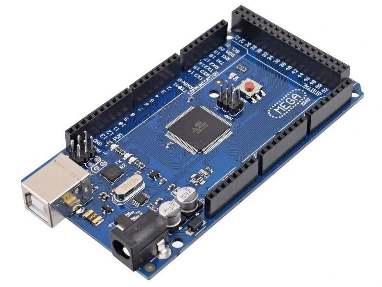
- Arduino Mega2560
- 3x KN3(C)-102AP toggle switch
- 1x PBS-33B Push Button
- 1x LED diode 5mm (red)
- 1x 330Ω resistor
And some links to used parts:
Related reading
In case you missed it, maybe you would like to dive into some articles from the stage 1 of building my flight simulator cockpit…
- My “home” cockpit
- Switches, dials and similar
- Instrument panel – DAVTRON Clock
- Instrument panel – Airspeed indicator
- Instrument panel – Attitude indicator
- Instrument panel – Altimeter
- PFD & MFD
- ELT Panel
- Compass
- Ventilation system
- Conclusion of the first phase, summary, and thanks
and stage 2: