
A few words for the introduction
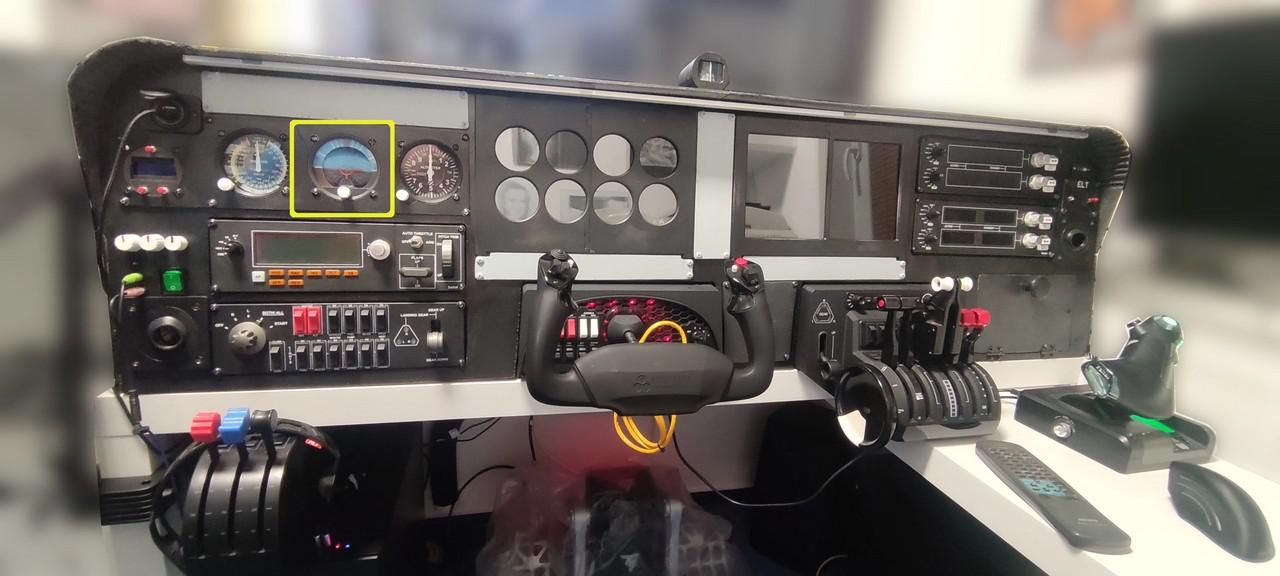
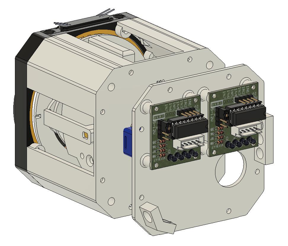
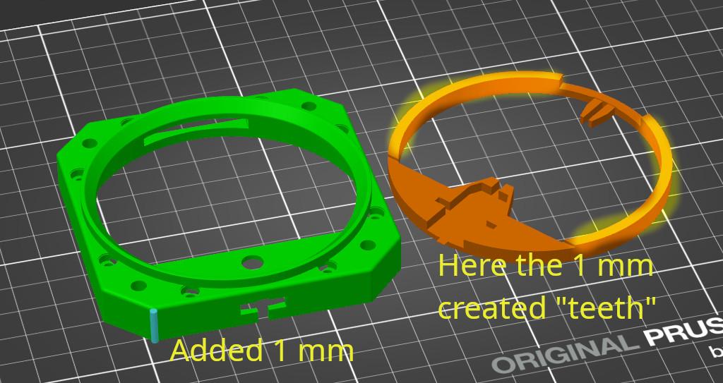
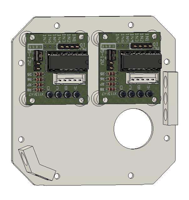
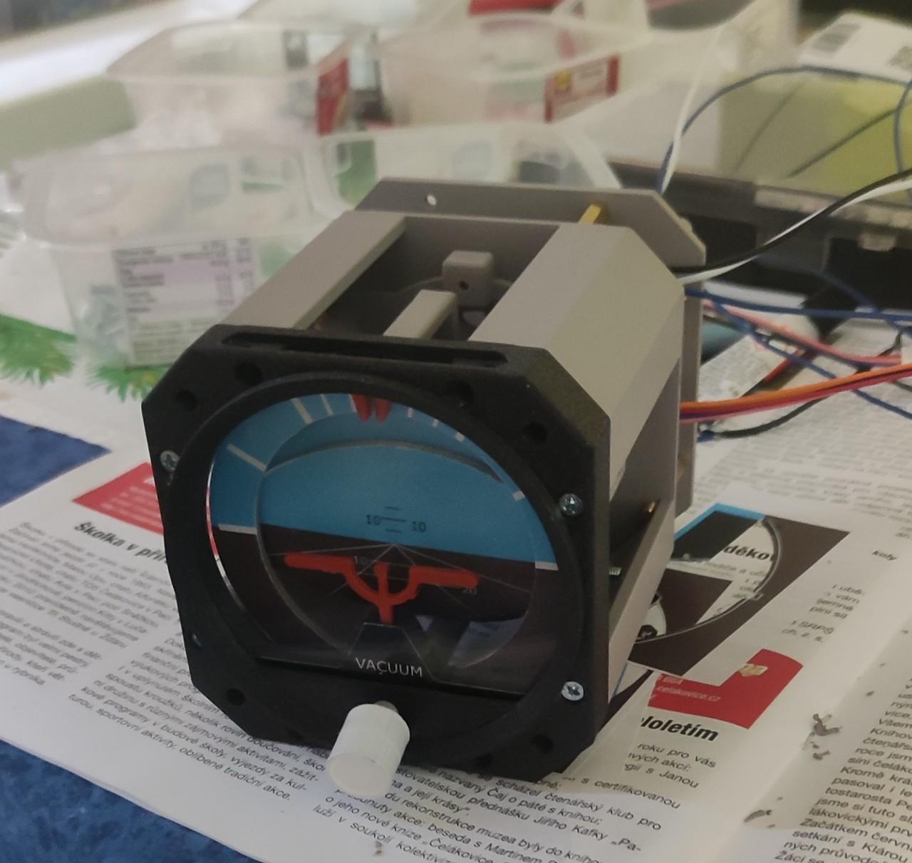
This gauge is in the middle one in my panel of backup instruments and I also completed it as the middle one, that is, second in order. This was the first instrument where I stumbled with a 3mm covering plexiglass and the original model from Captain Bob (subsequently also in other instruments). This required a minor adjustment to the depth of the fron frame/bezel and related parts. Here 1mm was enough for me and yes, reprinting parts because of 1mm can be a little nerve wracking :). The heart of the artificial horizon are two 28BYJ-48 stepper motors and their ULN2003 electronic control boards. As in the case of the altimeter, I designed a board for this control electronics, to which I can screw them and then screw the whole thing to the artificial horizon on the distance columns, so that it does not lie around somewhere else in the cockpit. Well, at least some value I added.
After the initial tests, I disassembled the artificial horizon one more time as part of the repetition, because of course I managed to put one of the magnets, which should be used in combination with the Hall sensor to automatically set the zero position, in the wrong direction. I already had it glued on so it went pretty well. But whatever, I probably inherited a bit of that perfectionism and I won’t get rid of it. You will surely be amused that in the end I don’t use the automatic setting of the zero position with MobiFlight with this instrument, because it works there so far in the way that MobiFlight starts rotating with a stepper motor until the set switch, in this case the Hall sensor, turns on. However, the artificial horizon is mechanically limited to movement only in a certain range of degrees, so neither one of the stepper motors can turn a full 360. Therefore, they can never find the zero position anyway because they will first hit one of their end limits. But it is ready there, in case, in the future, there will be an opportunity to define the direction and limits of the search for the zero value.
The source project for Autodesk Fusion, 3D printable models and links to the original video tutorial from Captain Bob can be found below.
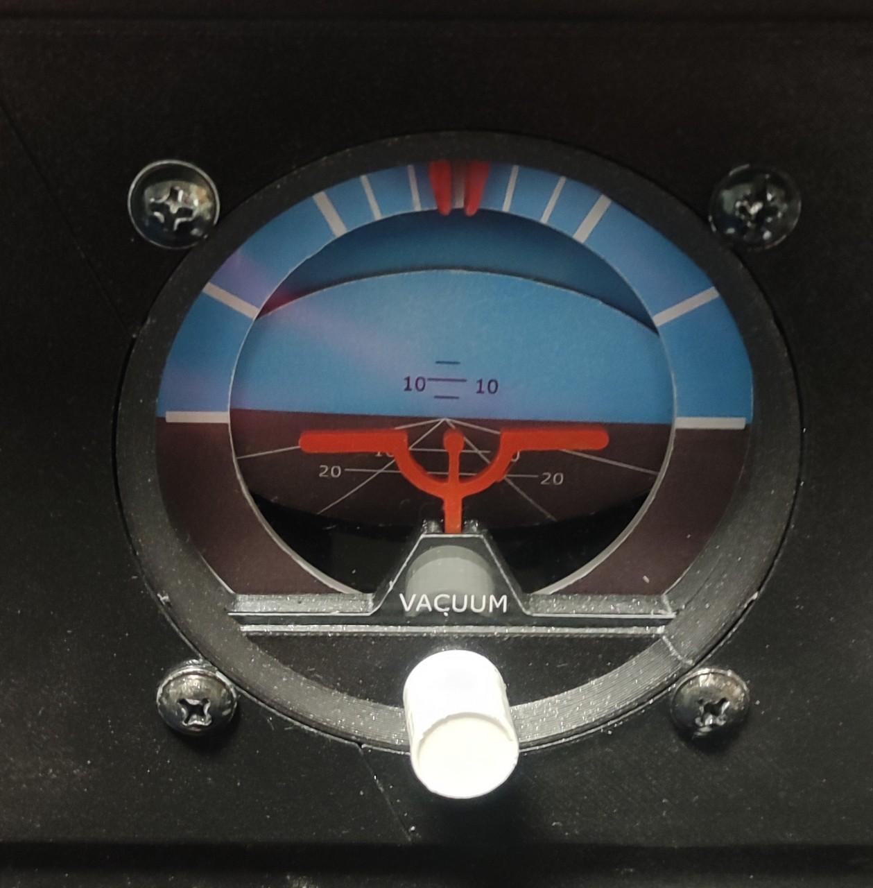
Gallery
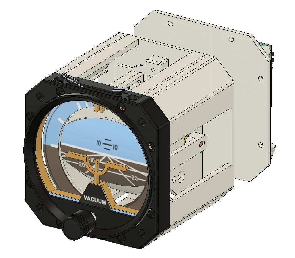
The description is a good thing, but the picture is just fine:

Wiring
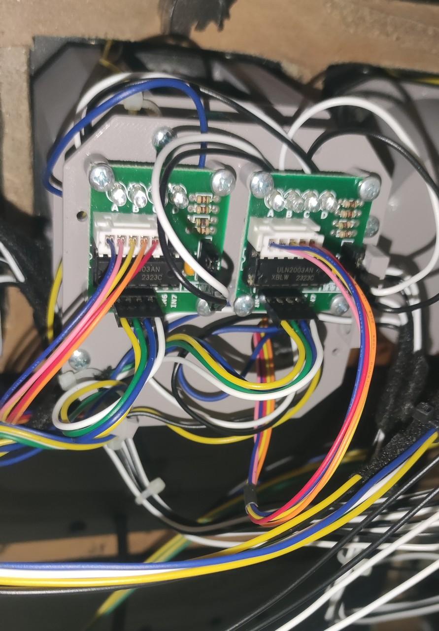
Below is a picture of the attitude indicator wiring.

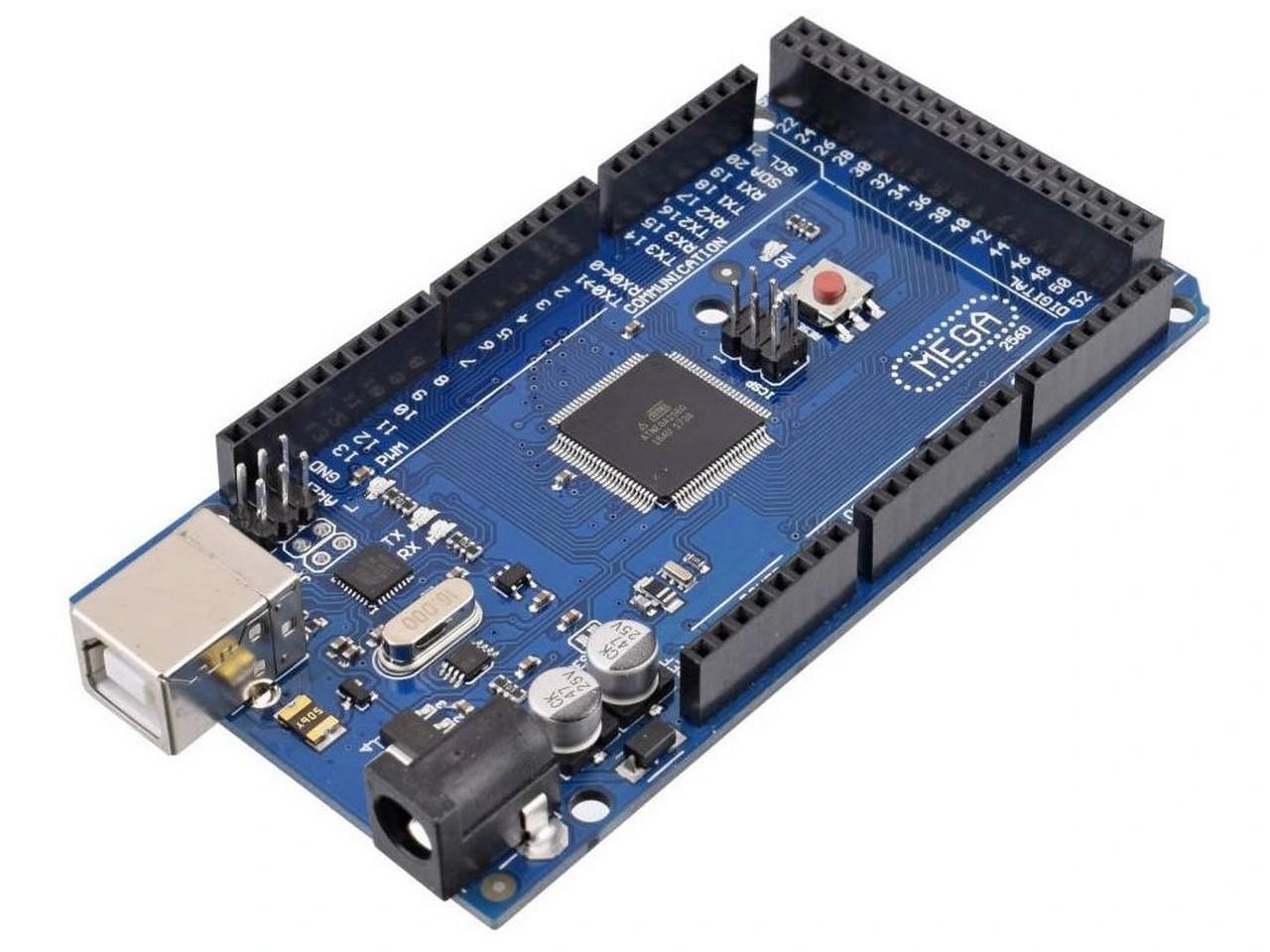
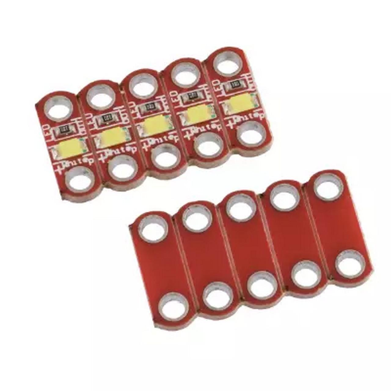
It’s not that complicated. The LED for the instrument backlight has an anode (white cable) connected to the PWM output of the Arduino Mega board and a cathode (black cable) to ground. It is a small LED on a printed circuit board with an integrated resistor. Here it was enough just to connect it by cables to the Arduino.
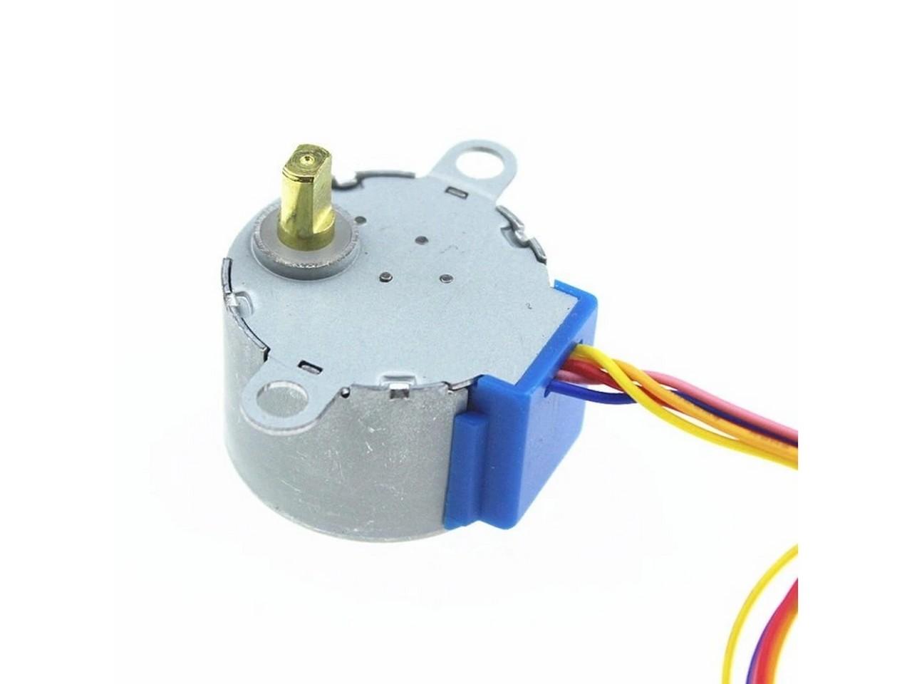
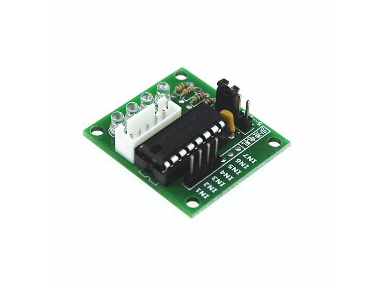
Furthermore, the artificial horizon uses two 28BYJ-48 stepper motors, which are part of most Arduino kits. Arduino controls these motors through ULN2003 or similar controllers. One motor controls the left and right tilt and the other controls the up and down tilt. The motor is connected to the controller, which is connected to the Arduino by four wires. The controller also requires power. It can be powered by an Arduino, but that would not handle it soon with the increasing number of components. So I used 5V from a computer power supply. The colors of the cables leading from the ULN2003 circuits to the Arduino are not important, it was rather a convention of mine (IN1 – yellow, IN2 – green, IN3 – blue, IN4 – white), which I may not have followed in all cases.
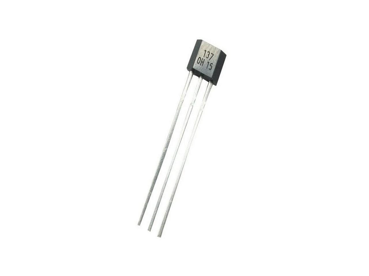
The picture also shows the connection of Hall sensors (type OH137), which, together with neodymium magnets, should be used to detect the zero position of each of the two axes. The Hall sensor has 3 contacts: “Ground” (black cable) is connected to the ground, “Power” (white cable) to the 5V power source and “Signal” sends a pulse when the sensor detects a magnetic field. It is connected both to 5V (white cable) via a 1kΩ resistor and also to the Arduino input (colored cables). So when the sensor detects a magnetic field, this output is 0V (LOW), otherwise it is 5V (HIGH).
You can also notice in the wiring diagram the connection of the GND pin from the Arduino to the negative pole (so also GND) of the external power supply. Connecting the GND pins of all circuits is important to create a common reference point, which allows for proper communication and functioning of all devices. Without a common ground, signals can be misinterpreted, leading to incorrect operation. Proper grounding also reduces electrical noise and improves the stability and safety of circuits. In practice, I solved this by connecting the GND output from the PC power supply to the GND pin on the Arduino. It is described in Chapter 2 – Switches, dials and similar.
Below is a gallery with used parts… hopefully they will help you find alternatives, when in a few months the links below will no longer be valid 🙁
Programming
Programming is described by Captain Bob in his videos, which you can find a link for below in the Links section. As for the operation of the LED diode for instrument backlighting, I describe that in the article about Compass. Here it works exactly the same.
Downloads
You can download an archive of my modified attitude indicator files below:
If you just want panels for mounting the electronics to the instruments:
And the files to print the instrument panel:
MobiFlight programming of the entire cockpit:
Links
Let’s start with the links to resources from Captain Bob….
- Video-tutorial on how to build attitude indicator from Captain Bob
- Captain’s Bob Website
- Captain’s Bob Cessna 172 project on Github
- Captain’s Bob source files for attitude indicator on Github
And some links to used parts:
- Arduino Mega2560
- 2x 28BYJ-48 stepper motor
- 2x ULN2003 stepper motor controller
- 2x OH137 TO-92S Hall Effect Sensor Switch
- 2x Neodymium magnet prism 3x3x1 mm, N50, nickel-plated – so that the hall sensor has something to react to
- 2x 1kΩ resistor
- SMD White LED Module for Lilypad Voltage 3v to 5v , 40mA
And used software:
All episodes of the series:
- My “home” cockpit
- Switches, dials and similar
- Instrument panel – DAVTRON Clock
- Instrument panel – Airspeed indicator
- Instrument panel – Attitude indicator – this one 🙂
- Instrument panel – Altimeter
- PFD & MFD
- ELT Panel
- Compass
- Ventilation system
- Conclusion of the first phase, summary, and thanks
Changes in this article
12.11.2024 – Added a paragraph about connecting the Arduino GND pin to an external power supply to create a common ground between all components (which is quite important and I didn’t have it there) to the Wiring chapter. The wiring diagram was also updated.