
A few words for the introduction
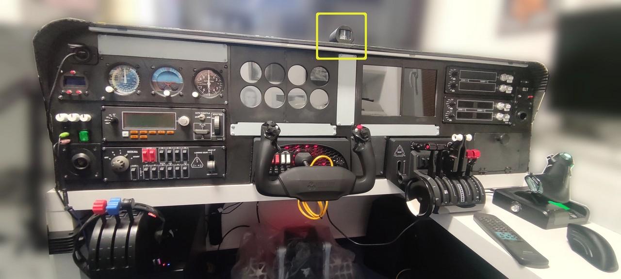
I have added the compass as last instrument, beyond the things I had planned for the first version of the cockpit, and only when the cockpit was almost finished. But it somehow occurred to me that it must not be missing and that it would not be so complicated. However, the project from Captain Bob did not include a complete compass, so I looked around for other ready-made models. In the end, I liked the most the GA Wet Compass from Thingverse.
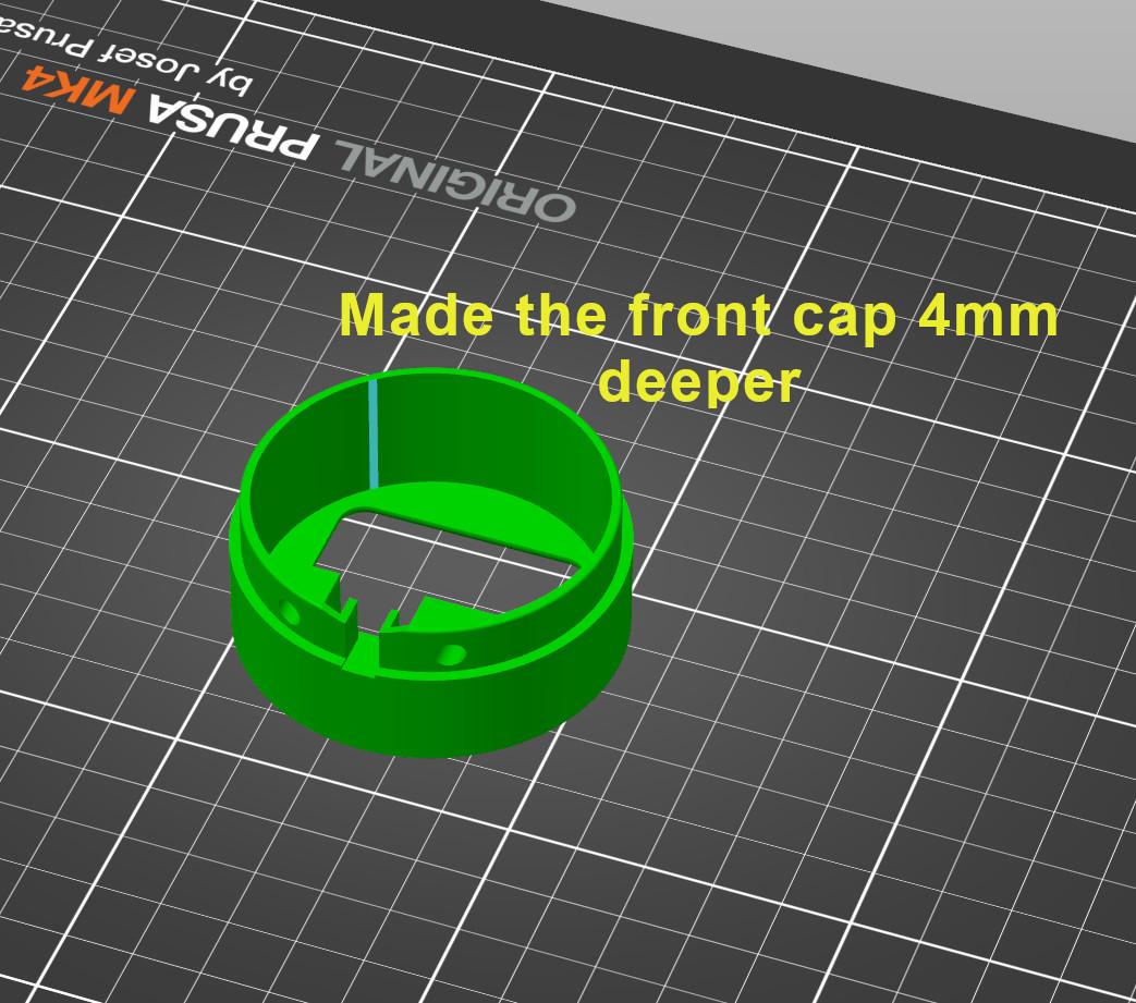
So I ordered the necessary electronic components and printed out the compass. I bought hobby plexiglass in Hornbach (hardware and home improvement store) and cut a cover glass out of it, as I didn’t want to leave the compass open. That kind of backfired to me, twice. First, I also had to adjust the depth of the front part (bezel) of the compass (+4mm) because it didn’t want to fit together with the added 2mm thick plexiglass. And the second time, after about the second hour of testing the entire cockpit, the sticker on the compass rose started to come off and so I had to disassemble the compass again.
In addition to the original design, I glued an LED diode on the upper wall of the compass so that the instrument can be illuminated just like the airspeed indiator, attitude indicator and the altimeter. But it didn’t require any modifications to the 3D model, just a hot glue gun.
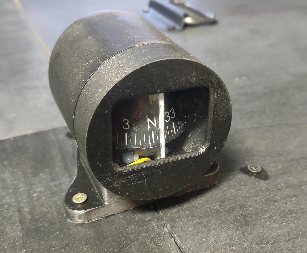
Gallery
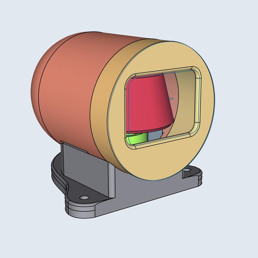
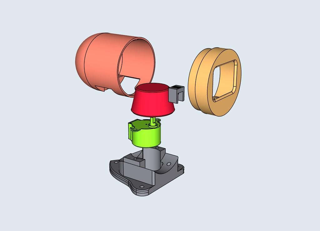
The description is a good thing, but the picture is just fine:
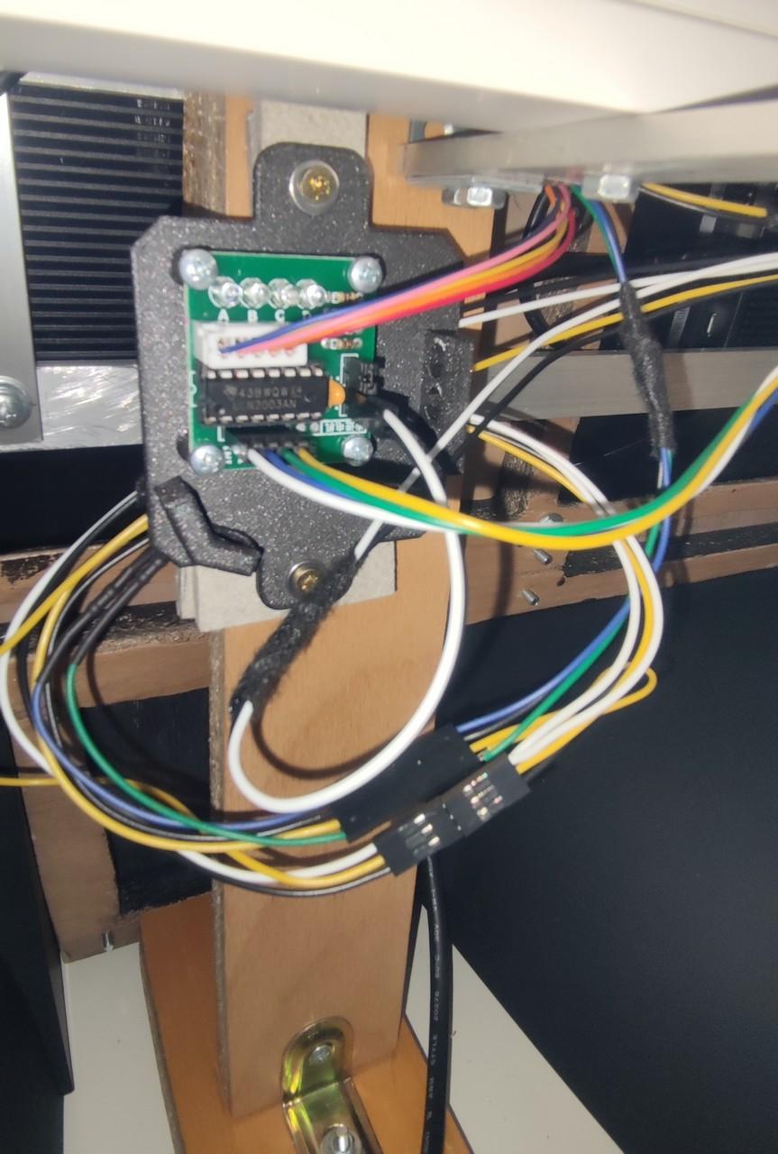
Wiring
Below is a picture of the compass wiring.

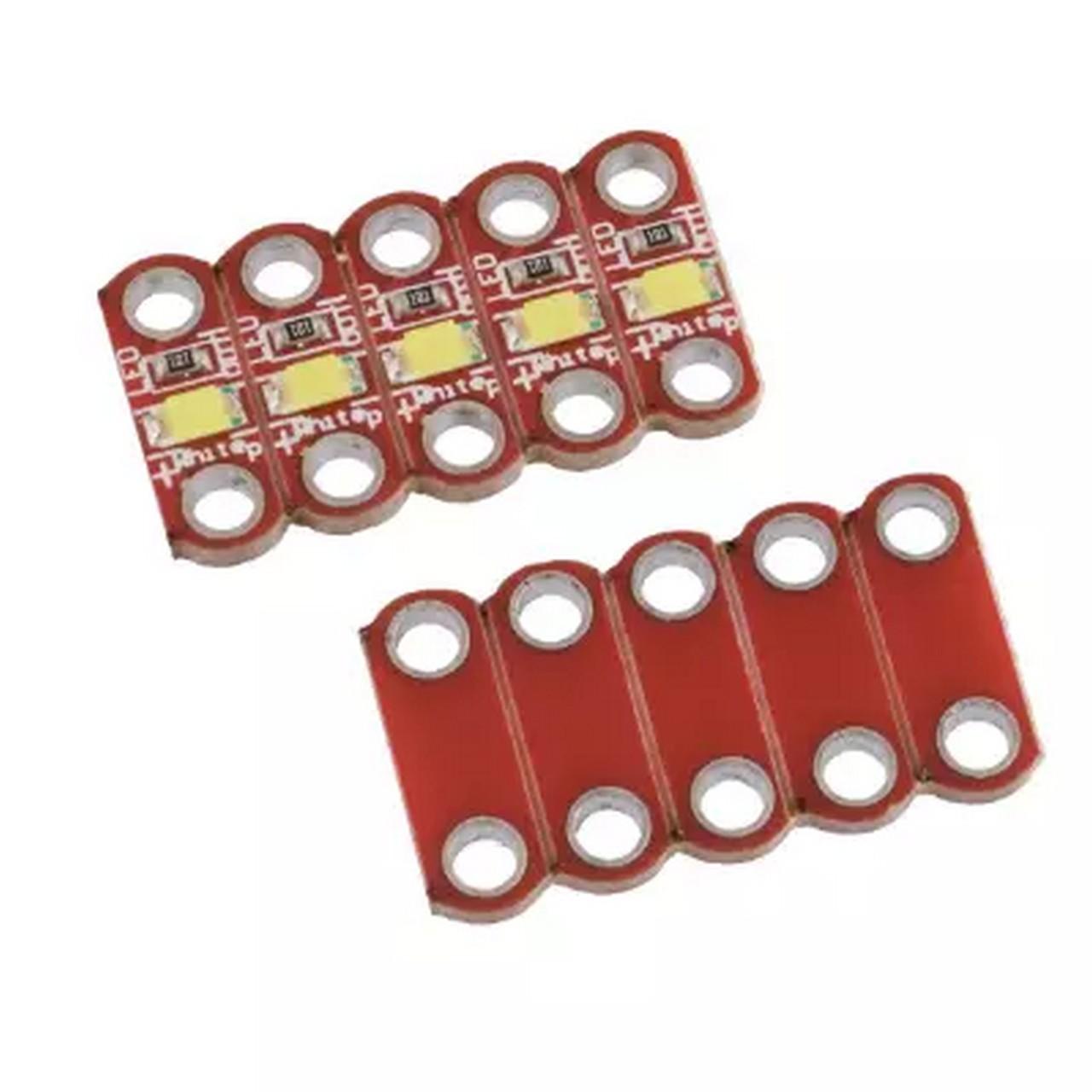
It’s not that complicated. The LED for the instrument backlight has an anode (white cable) connected to the PWM output of the Arduino Mega board and a cathode (black cable) to ground. It is a small LED on a printed circuit board with an integrated resistor. Here it was enough just to connect it by cables to the Arduino.
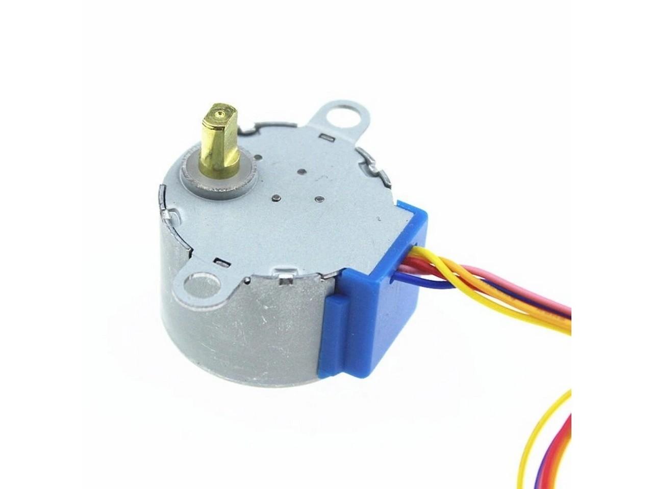
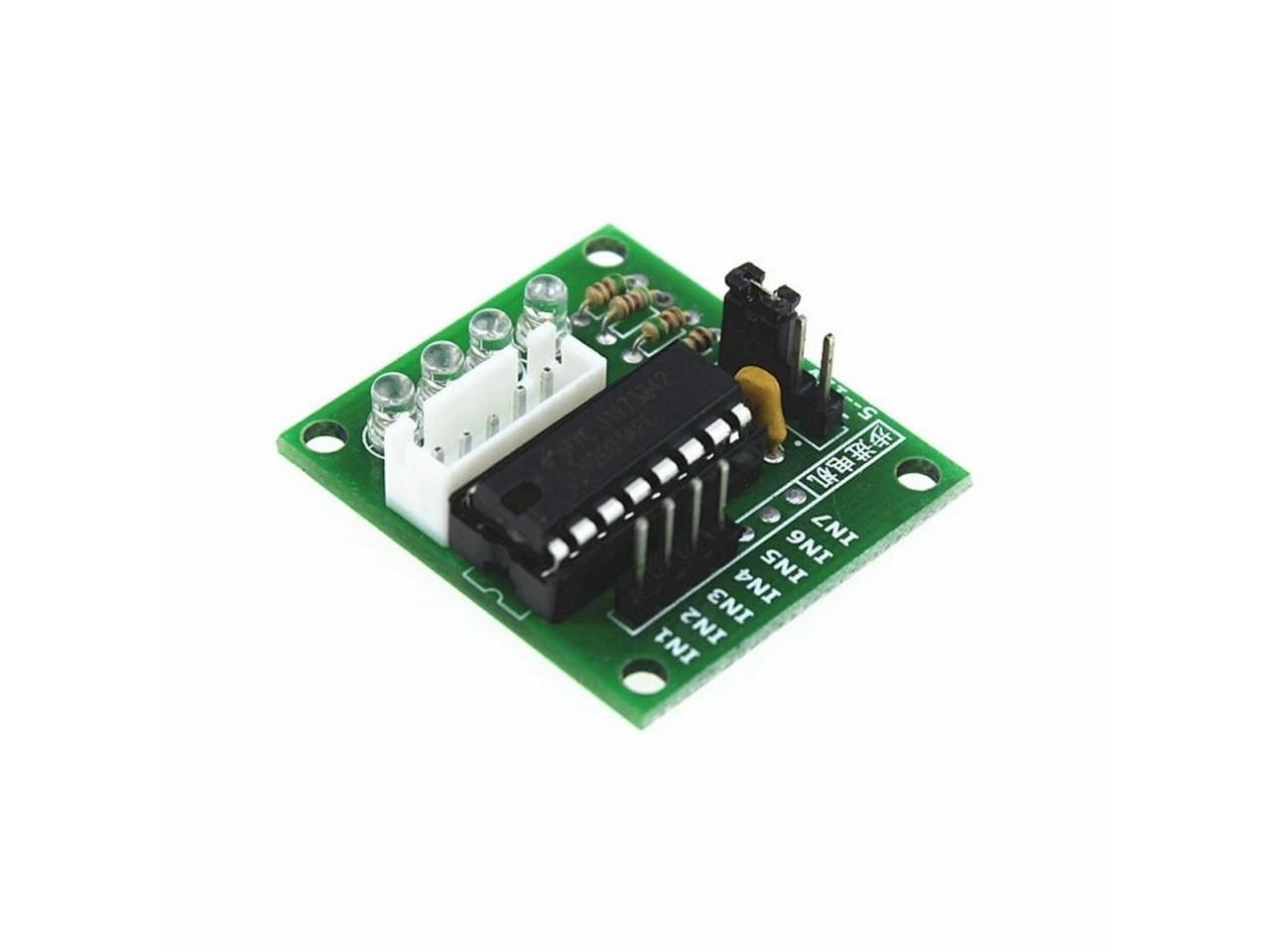
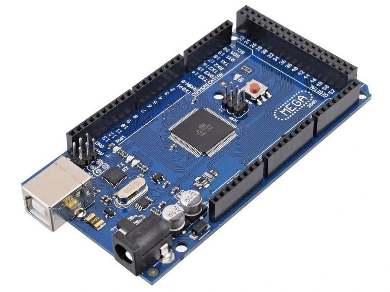
The compass rose rotates with the help of a single 28BYJ-48 stepper motor, which is part of most Arduino kits. Arduino controls these motors through ULN2003 or similar controllers. The controller also requires power. It can be powered by an Arduino, but that would not handle it soon with the increasing number of components. So I used 5V from a computer power supply. The motors are connected to the controllers and the power supply, and the controllers are connected to the Arduino board by four wires (the colored ones) . MobiFlight then moves the hands of the altimeter through all this electronic symbiosis. The colors of the cables leading from the ULN2003 circuits to the Arduino are not important, it was rather a convention of mine (IN1 – yellow, IN2 – green, IN3 – blue, IN4 – white), which I may not have followed in all cases.
Automatic setting of the zero / initial position also works with the compass. In the case of the attitude indicator, it was solved with a magnet and a Hall sensor. Here, on the other hand, the author of the original instrument had already designed an optocoupler, and I also wanted to try its use, so I did not change it. Simply put, the optocoupler sends out an infrared beam and examines whether and at what intensity it returns. When the beam hits a surface with reflective properties, the optocoupler reacts to it more than if we point it into space. So I drew a line on the bottom of the compass rose with white acrylic paint to represent the zero position. It was supposed to be in the position of north , but I missed it by a few degrees. But that doesn’t matter, it can be corrected in MobiFlight.
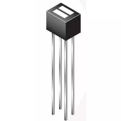
Anyway, connecting the optocoupler may seem a little more complicated. It already has 4 contacts. Of course, you should always read the documentation of the optocoupler you have. I used the type QRD1114. The optocoupler is actually two components in one. In one half, it contains an infrared diode that emits that light beam and then in the other half is phototransistor that reacts to the returning beam (if there is one). Each of these parts needs two wires. The infrared diode has an anode (A) connected to the supply (5V) (white cable) through a 330Ω resistor (blue cable) and a cathode (black cable) to ground. The phototransistor, it tells us when the optocoupler detected the return of the beam. The collector (C) is also connected to the power supply (5V) (white cable), this time through a 10kΩ resistor and at the same time to the input on the Arduino board (yellow cable). The emitter (E) is then connected to ground (black cable). This connection then works in such a way that if the optocoupler sees the white line on the compass rose, there is 0V (LOW) at the Arduino input, and if it does not see it, there is 5V (HIGH).
You can also notice in the wiring diagram the connection of the GND pin from the Arduino to the negative pole (so also GND) of the external power supply. Connecting the GND pins of all circuits is important to create a common reference point, which allows for proper communication and functioning of all devices. Without a common ground, signals can be misinterpreted, leading to incorrect operation. Proper grounding also reduces electrical noise and improves the stability and safety of circuits. In practice, I solved this by connecting the GND output from the PC power supply to the GND pin on the Arduino. It is described in Chapter 2 – Switches, dials and similar.
Below is a gallery with used parts… hopefully they will help you find alternatives, when in a few months the links below will no longer be valid 🙁
Programming
Since the compass programming was already my work – based on experience and watching Captain Bob’s procedures with his instruments, I will try to describe it a little here. Again, there is no space here to get bogged down in the basics of working with MobiFlight, in the deeper context of how it works with simulators, what is Offset or a simulator variable. I expect you to know it and if you don’t, you’ll have to learn elsewhere 🙁 I’ll just write what variables I used, what transformations and roughly why.
Configuring the stepper motor for automatic zero/initial position setting
I’ve received a question about how the automatic setup of initial position on the compass is programmed, which made me realize that I actually forgot to describe it here, even though it is pretty simple. MobiFlight will take care of that automatically, you just need to set one option when configuring the servo that drives the compass rose.
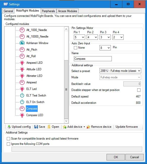
On the picture above you can see the setup of servo that drives the compass rose in my cockpit. What you need to setup for automatic initial position set is the Auto Zero Input section.
Just set here the PIN (You need to deselect the None option first) to which is connected the trigger that will tell MobiFlight that the servo is in zero/initial position. In this case, I’ve set PIN 8. The yellow wire from the QRD1114 optocoupler is connected to that PIN (as you could see on the wiring diagram earlier in this article). So when MobiFlight profile runs and does the initialization, MobiFlight will turn the servo until it senses a change on that PIN. Which will happen, when the optocoupler senses the white line on the bottom of the compass rose. Then MobiFlight stops the servo. That is all that is needed for the automatic set of zero/initial position function to work.
Programming the movement of compass rose
Programming the compass is one entry in MobiFlight on the “Output configs” tab, i.e. where the “output behavior” is defined and after you have defined the 28BYJ-48 stepper motor as one of the outputs on the Arduino – I assume you know how. So let’s dive into that one line that tells the Arduino what to do with the stepper motor.
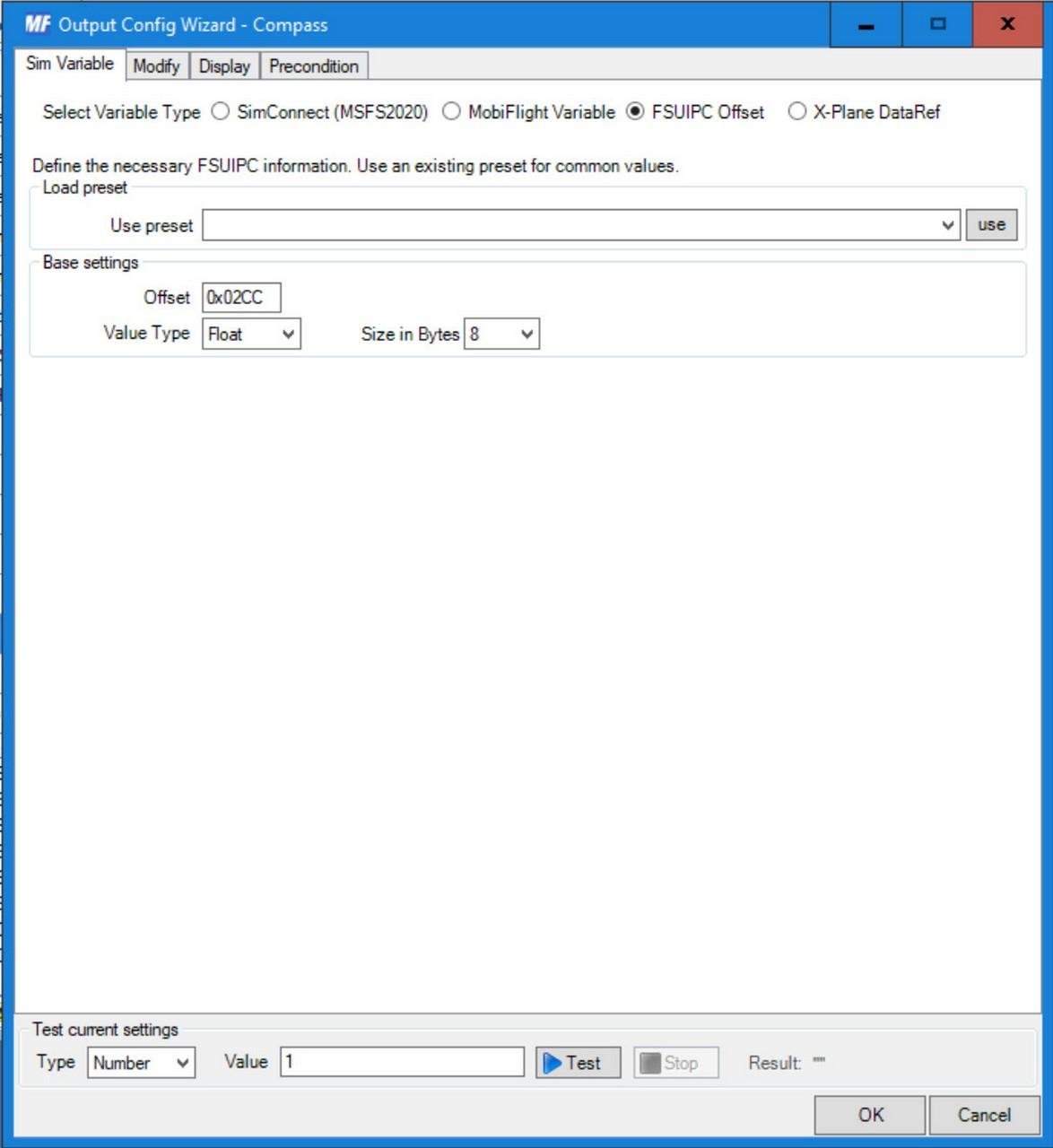
I used FSUIPC Offset – 0x02CC as the source of information on the Sim Variable card. In the FSUIPC documentation on offsets, you would find that at this offset you will find the value of the indicated degrees on the compass – that is, the value that the compass shows in the simulator. And that’s what we want the physical (printed) compass to show us. The value at the offset is an 8-byte Double, so in MobiFlight we set the Value type => Float (it does not have a Double directly) and the size in bytes to 8. So now MobiFlight knows that it should read the compass data, which will be a decimal number between 0 and 360. But what about that? We want to rotate the stepper motor accordingly so that the physical compass shows us the same value. Well, let’s jump to the Display tab now:
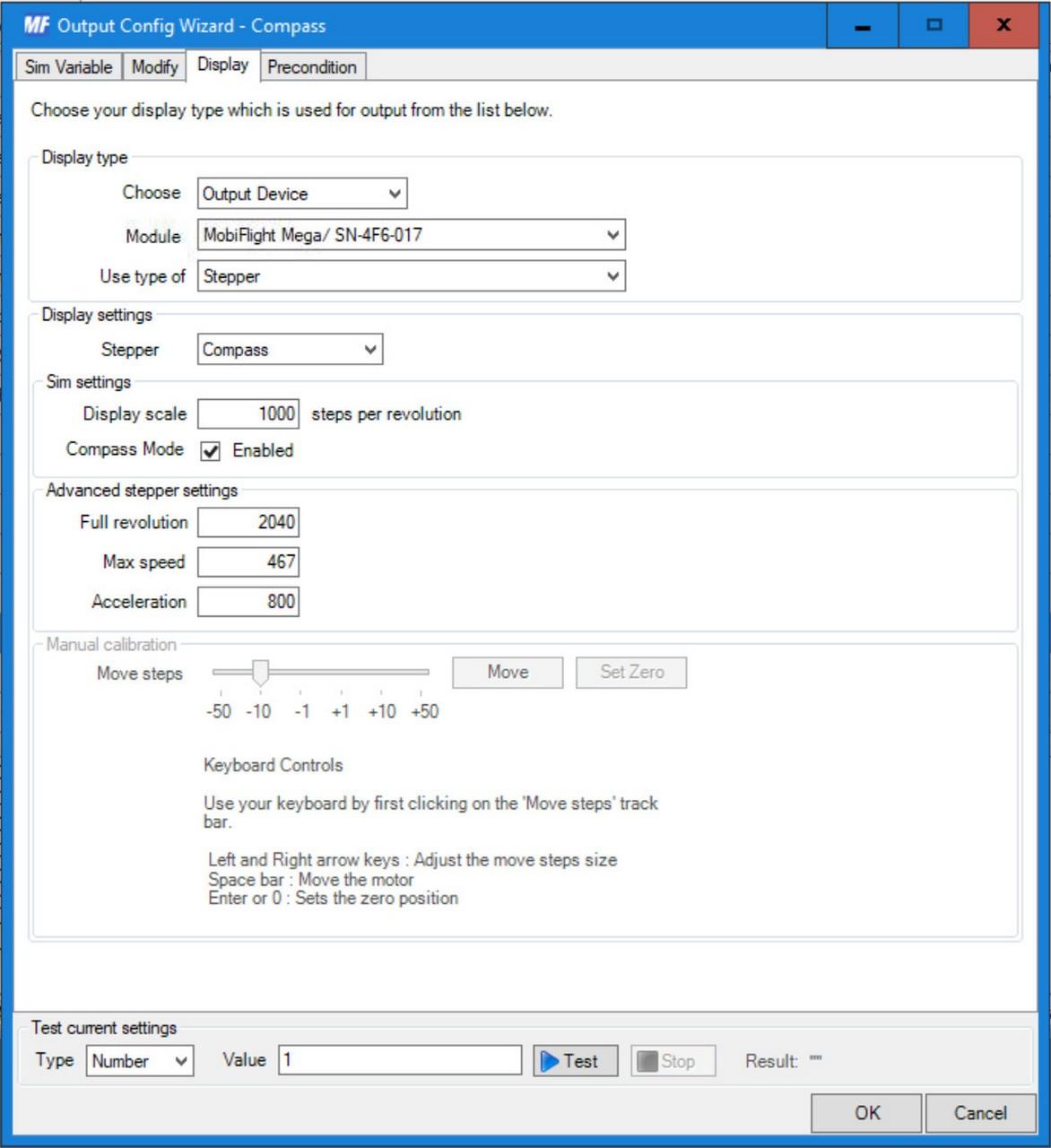
Here, in the “Display type” section, we select the parameter Choose => Output Device, Module => Arduino board to which you have connected the stepper motor from the compass and Use type of => Stepper. In the “Display settings” section, select Stepper => the stepper motor that controls the compass. We will set the Display scale to 1000 (I think it is the default value). Compass Mode must be checked. This actually says “Hey, when you turn the stepper motor a full 360 degrees, don’t go back to zero but keep going…”. If you don’t check this, the compass would always rotate 360 degrees in the opposite direction after reaching a full 360 degree rotation, and then patiently start rotating the next value. I think the values in “Advanced stepper settings” are default, but make sure to match your values with the ones from the picture. They are related to rotation speed and fall into the “we won’t drill into them now” category. Go back to the Modify tab we skipped:
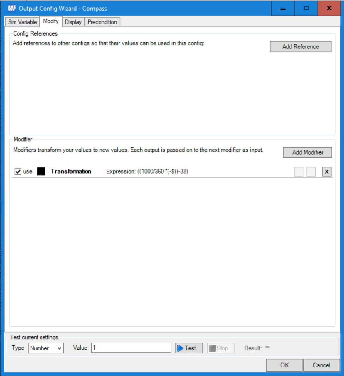
In this tab, it is possible to make a completely different value from the value that MobiFlight gets from the simulator. Here, for example, MobiFlight receives a decimal number from the simulator from 0 to 360. But the stepper motor expects MobiFlight to send it a value from 0 to 1000 – which is the rotation of the stepper motor by 360 degrees. Yes, we could set the stepper motor’s Display scale on the Display tab to 360 to balance it out. But then we would kind of loose the advantage of the precision of the decimal number, because we could actually only rotate the stepper motor in whole degrees. A resolution of 1000 will allow a finer rotation of the compass rose. But we have to graft the value of 360 to 1000. Use the Add Modifier button to add the Transformation type modifier and write the expression from the picture into Expression:
((1000/360*(-$))-38)(1000 / 360 * (-$)) – this is the conversion by which we graft the value 0-360 from the simulator onto the resolution of 1000 of the stepper motor. $ in MobiFlight represents the value obtained from the simulator. The minus is in front of it due to the direction of rotation of the stepper motor. This is what you have to find out by try, if the motor turns to the opposite side than you want, you have to change the polarity of the value that MobiFlight sends to it. In this case, I had to use minus to get my compass to rotate correctly with the compass in the simulator. And the -38 is my compensation for the “zero value” of the compass. Do you remember how I wrote somewhere in the wiring that I did not draw the white line at the bottom of the compass rose, with the help of which the optical sensor, or rather MobiFligh, recognizes where my compass has zero value (north) , inaccurately? This is how I corrected it. So that’s also the number you have to find by trial and error.
Programming the “backlighting” of the compass
As you know, the compass, as well as the trio of backup devices – airpseed indicator, attitude indicator and the altimeter contain an LED diode for “backlighting” – the lighting of the instrument. I will describe its programming below (all the instruments have it like a copier).
After adding the entry in MobiFlight, we start again on the Sim Variable tab:
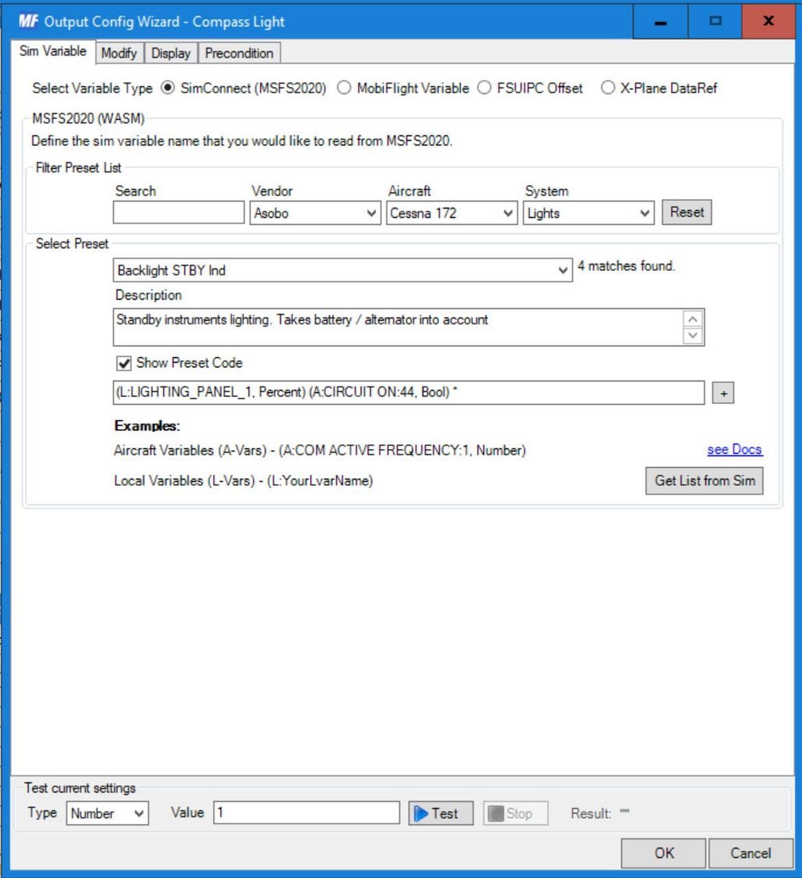
For the time being, I used the “predefined” variable from MSFS – Backlight STDBY Ind from the Cessna 172 aircraft as a source variable for the backlight. I haven’t found a more universal one yet. It takes on a value of 0-100 (in percentages). According to this value, we want to control the brightness of the diode by PWM modulation. In MobiFlight, this means sending a value from 0 to 255 (0 – off, 255 – maximum lighting) to the output where the diode is. We define the necessary transformation on the Modify tab:
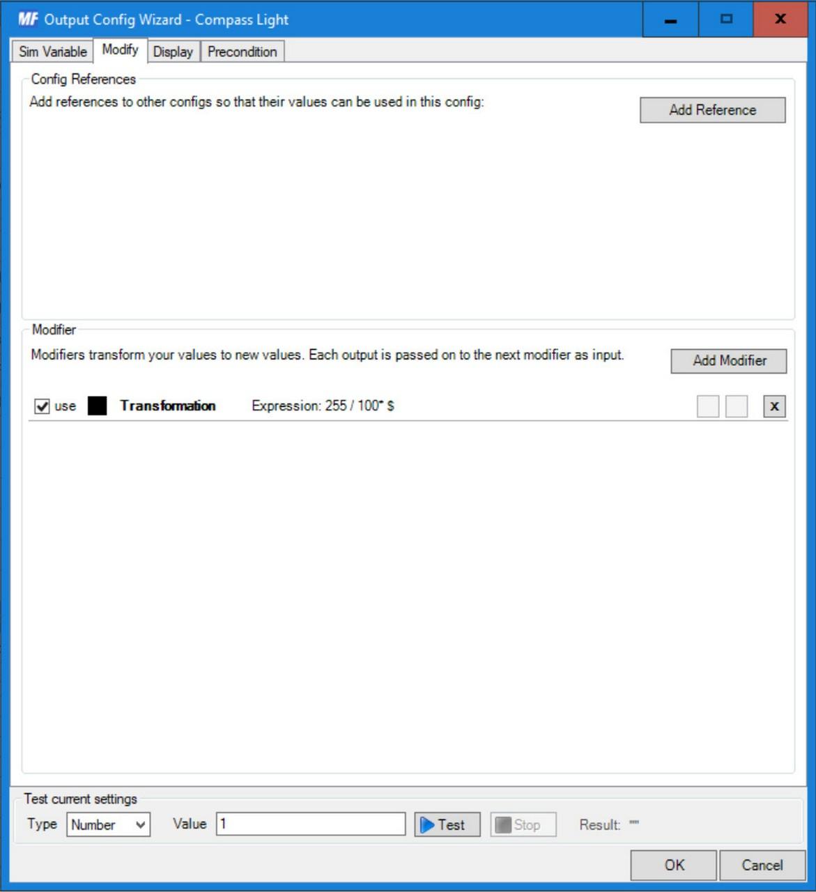
255 / 100 * $This expression, which recalculates the value 0-100 to 0-255, probably does not need to be explained further 🙂
All that remains is to define on the Display tab is that according to this calculated value, MobiFlight should set the PWM output on the given LED.
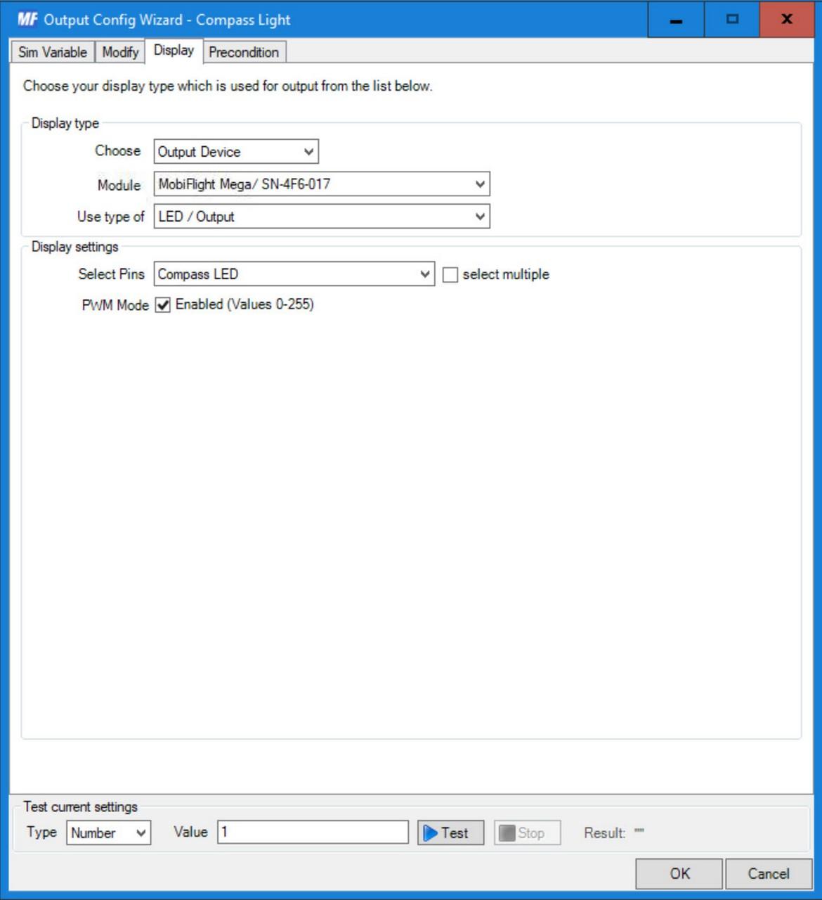
In the “Display type” section, we set Choose => Output Device, Module => Arduino board to which the LED is connected, Use type of => LED / Output. In the “Display settings” section, then Select Pins => the LED of the compass (or any other device) and check the PWM Mode option (without this, it would only work as on/off, without brightness control).
Downloads
Below you can download an archive that contains both the original compass files from Thingeverse and my modified and added files:
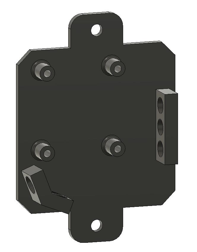
If you just want panels for mounting the electronics to the instruments:
MobiFlight programming of the entire cockpit:
Links
Let’s start with the links to the source files….
- GA Wet Compass (https://www.thingiverse.com/thing:4810513)
And some links to used parts:
- Arduino Mega2560
- 28BYJ-48 stepper motor
- ULN2003 stepper motor controller
- ONSEMI (FAIRCHILD) QRD1114 reflex optocoupler
- 330Ω resistor
- 10kΩ resistor
- SMD White LED Module for Lilypad Voltage 3v to 5v , 40mA
- Hobby plexiglass, 2mm thick – I used it to cut the covering glass for the compass
And used software:
All episodes of the series:
- My “home” cockpit
- Switches, dials and similar
- Instrument panel – DAVTRON Clock
- Instrument panel – Airspeed indicator
- Instrument panel – Attitude indicator
- Instrument panel – Altimeter
- PFD & MFD
- ELT Panel
- Compass – this one 🙂
- Ventilation system
- Conclusion of the first phase, summary, and thanks
Changes in this article
6.11.2025 – Added the Configuring the stepper motor for automatic zero/initial position setting chapter about how automatic set of zero/initial position is configured, which I forgot to describe.
12.11.2024 – Added a paragraph about connecting the Arduino GND pin to an external power supply to create a common ground between all components (which is quite important and I didn’t have it there) to the Wiring chapter. The wiring diagram was also updated.