Let’s start “lightly”…
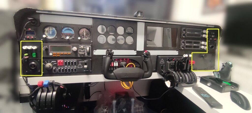
If you look at the photo of the cockpit, you will find several controls on it’s main panel that do not fit into any functional group and are also all independent of whether the simulator is running or not. Only the electrons, i.e. the power supply, must run. It’s probably much easier for me to write, now, that I have it assembled, than for you, trying to find it in the picture in the second article about the cockpit 🙂
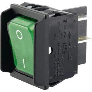
The electrons are released into the entire cockpit by the main green switch, which turns on/off the 220V socket inside the cockpit, from which everything is then powered.
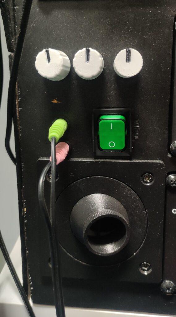
Above this green switch are three rotary knobs. The first of these, on the left, drives a trio of “Ventilation” fans. But it has its own chapter.
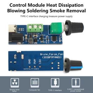
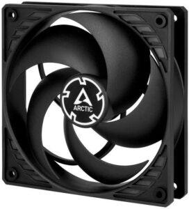
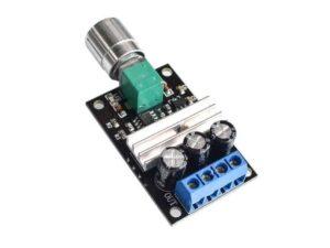
The middle knob controls a pair of fans on the sides of the cockpit, that’s “avionics cooling”. These fans are intended to draw air through the cockpit to cool it during the hot summer months. These are classic 120mm PC fans and are controlled by a simple circuit from AliExpress that needs 12V at the input (either DC connector or USB) and outputs are just connected to those fans (plus, minus and control PWM signal).
The third knob, on the right, controls the “Panel flood light”, a LED strip hidden under the upper edge of the dashboard (glare shield). It is of course used to illuminate the panel at night and is dimmable.
To the left of the main power switch is a pair of audio jacks for headphones. They are only connected to the audio inputs/outputs on the computer with a cable and the necessary terminals.
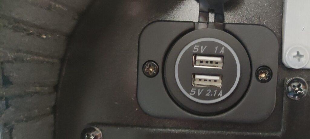
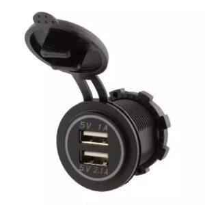
In the upper left corner there is a pair of USB ports that can be used to charge a phone or tablet, or anything else. They are only used for charging, they are not data-linked to anything.
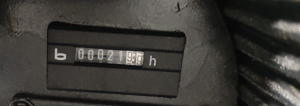
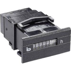
In the upper right corner is an operating hours counter that turns on when the electrons start flowing and turns off when they stop.
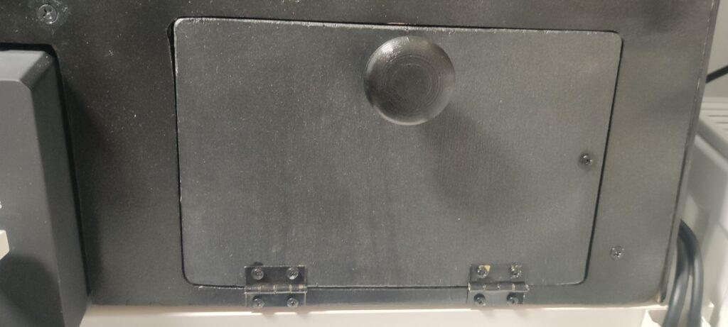
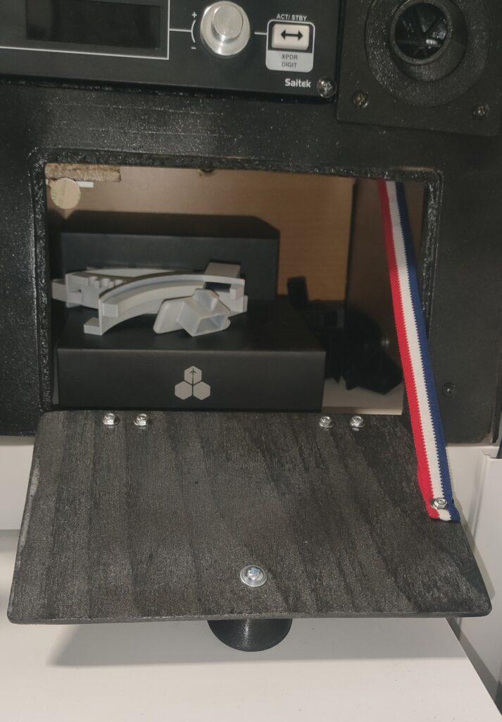
There is a “glove box” in the lower right part of the cockpit. I don’t really need gloves during simulator flying, so this space serves well for storing various throttle and other levers for the Honeycomb Bravo Throttle Quadrant, or other replaceable cockpit accessories.
Wiring
I have described it a bit above, but let’s show something. It’s simple – as easy to say when you’ve done it 🙂 Below is a picture of the fan wiring for “avionics cooling”:

There are two 12V PC fans, 120mm, with PWM speed control. These are controlled by a small circuit from AliExpress. It requires a 12V input, which is possible either via a classic DC connector (5.5/2.1) or via USB. In my cockpit, a lot of components are powered by a classic computer power supply, where I used branches for powering disks and similar accessories as a source for +5V and +12V. I cut off the MOLEX terminals and brought the wires to the terminal block, which I have divided into a section for 5 and 12V. It can be seen in the cockpit gallery in the introductory article. Cables then go from this terminal block to the necessary appliances, as here, to the mentioned circuit. Two fans, each with 3 cables, are connected to the output of the circuit. It’s 12V and ground (GND), that’s a white and black cable. The third, blue, controls the fan speed by PWM modulation. The “ventilation” system, which has its own article, is connected exactly the same, with the only difference being that there are 3 fans.
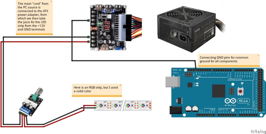
The circuit for controlling the illumination of the cokcpit panel using the LED strip is wired in a very similar way. The LED strip is dimmable and is also controlled by a small circuit using the PWM modulation method. The only difference is that this circuit is powered directly from the PC power adapter as shown in the image above.
You can also notice in the wiring diagram the connection of the GND pin of the Arduino to the negative pole (so also GND) of the computer power supply adapter. Connecting the GND pins of all circuits is important to create a common reference point, which allows for proper communication and operation of all devices. Without a common ground, signals can be misinterpreted, leading to incorrect operation. Proper grounding also reduces electrical noise and improves the stability and safety of the circuits. I kind of forgot about this and this connection was the fastest way to fix it for the entire cockpit, or whatever is not powered by the Arduino, is powered by the PC power supply.
Below is a gallery with used parts… hopefully they will help you find alternatives, when in a few months the links below will no longer be valid 🙁
Downloads
Below you can download some 3D parts that I used when building the cockpit – such as knobs for potentiometers or various holders. Most, if not all, were freely available on sites like Thingverse and the like. So they’re not my work, but luckily they can be re-shared here so you don’t have to search and download them all. But if you want, the links are below 🙂 Inside the archive you will find other archives, which are raw source archives with the given components. Each of them contains information about the license, so if possible, familiarize yourself with it before using the respective objects.
Links
To power the various parts of the cockpit:
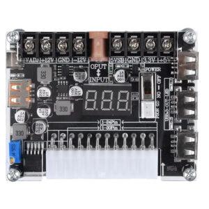
- Electronic circuit for using the PSU as a power source: 20/24 Pin Atx Power Adapter Board Power Module Adapter Adjustable Voltage With Red Digital Display Support For Pd2.0/Pd3.0
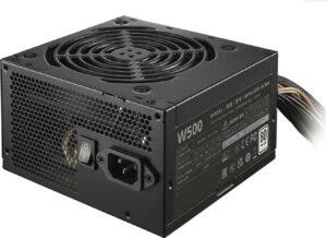
- Cooler Master ELITE NEX WHITE 500 230V PSU
- Renkforce 615B-CMW-S power socket strip with surge protection 6x white DE schuko plug/sockets – this is mounted inside the cockpit to power the screens, Arduino etc.
For “ventilation” and “avionics cooling”:
- PWM module for fan control: DC 5V 12V Fan Governor Control Module Knob Control Strong Fan Drive Board Pwm Governor Welded Smoke Exhaust Fan Control Board
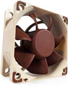
- 3x Noctua fan NF-A6x25 PWM 4-pin, 3000 RPM, 60x60cm – fan for ventilation system
- 2x ARCTIC P12 PWM – fan for “avionics cooling”
I couldn’t find reasonable alternative links for english shops, so I kept there links for the czech shop that I have used. You may open them via some translator to get some description and find alternatives in your location.
- LED strip 9.6W/m 12V without IP20 protection
- PWM motor speed controller 3A – for controlling the brightness of the LED strip for the panel lighting
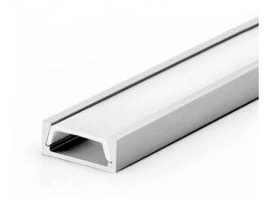
- Wall profile for LED strips – micro
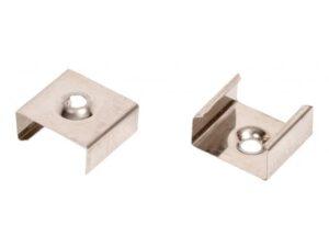
- Profile holder – micro
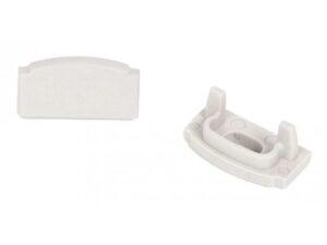
- Micro profile end for snap-on diffuser – Opened end
- Micro profile end for snap-on diffuser – Full end
- Black cable
Other panel components:
- DS-2015 USB socket to the panel
- Bauser 252.2/008-001-1-1-001 252.2/008-001-1-1-001 Nejmenší počitadlo provozních hodin – 252,2
- Marquardt 1835.3608 Toggle switch 01835.3608-00 250 V AC 16 A 2 x Off/On IP40 latch
3D printed parts for the cockpit:
- Arduino Mega / Mega 2560 / Due Drilling And Mounting Plates – holder for Arduino Mega2560
- Socket Wallmount for Renkforce 615B – holder for power socket rail
- Cabinet knob with nut – Button on the door at the “glove box”
- Boeing 737 Map & Chart Panel Knobs z projektu 737DIYSIM – control knob for the main panel lighting
- Some knobs from 737 Dimming Panel Knobs project of 737DIYSIM – control knobs for “ventilation system” and “avionics cooling”
All episodes of the series:
- My “home” cockpit
- Switches, dials and similar – this one 🙂
- Instrument panel – DAVTRON Clock
- Instrument panel – Airspeed indicator
- Instrument panel – Attitude indicator
- Instrument panel – Altimeter
- PFD & MFD
- ELT Panel
- Compass
- Ventilation system
- Conclusion of the first phase, summary, and thanks
Changes in this article
12.11.2024 – Added a paragraph about connecting the Arduino GND pin to an external power supply to create a common ground between all components (which is quite important and I didn’t have it there) to the Wiring chapter. The wiring diagram was also updated.

