

A few words for the introduction

Circuit Breaker panel is another part of the cockpit that I started to build on the foundations of Captains Bob’s C172 cockpit. But this one appeared to be a little bit more challenging. Starting with a little hiccups such as that the electromagnets that Captain Bob used ,were no longer available. So, I had to order similar ones and of course, had to made small adjustments in the 3D printed files.
The other thing is that the “circuit breakers part” of the Captain Bob’s C172 cockpit is also a little bit “work in progress” … the wiring and programming documentation is incomplete so it is not a straight and simple “DIY” solution you could follow. But the experience I gained while building the other cockpit stuff came in handy on this one.
Gallery
The description is a good thing, but pictures speaks better:


In the gallery you can see the Circuit Breaker Body – which is the element in which the electromagnet and switch will be mounted. All together makes the simulated circuit breaker that will be mounted into panel. There are 2 images showing my panel design with mounted circuit breakers bodies. Of course, this panel is specific for my cockpit as it has irregular shapes. But I think you get the idea. The last two images shows the “electronics mounting box”, because the simulated circuit breakers need more stuff… Like a place where the wires meet and where the relay board (which actually controls the electromagnets) will be.
Wiring
Below is a picture of the circuit breaker panel wiring:
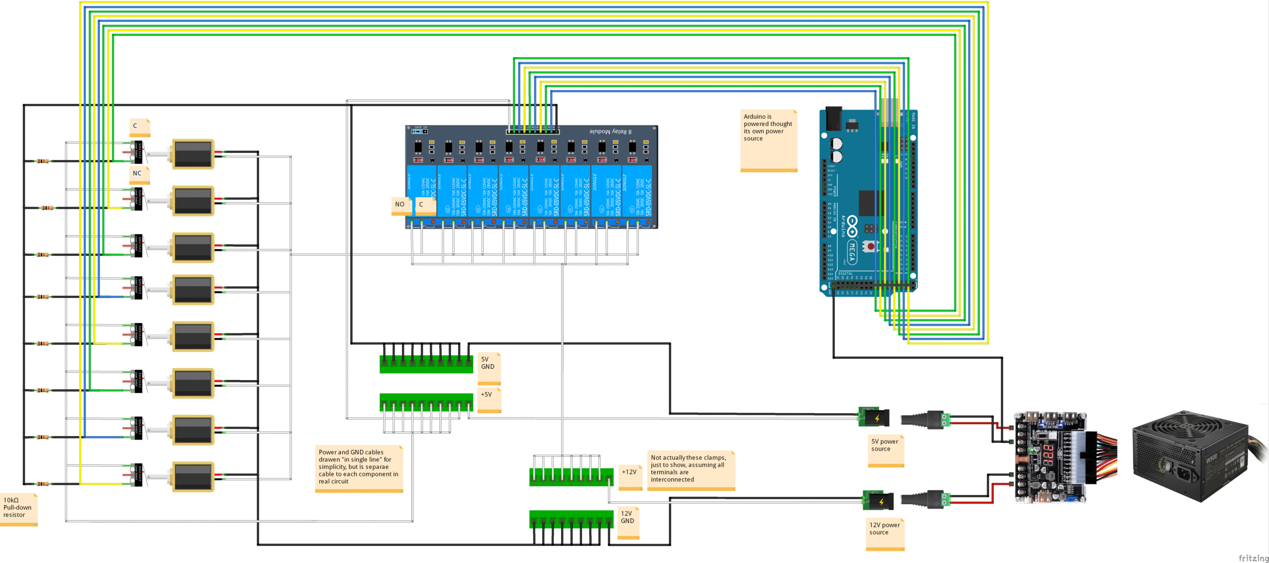
Ok, the circuit breaker “circuit” has a little bit more wires than any that I covered so far in my cockpit building articles. There is an Arduino Mega 2560 board (on the right top side of the diagram) which will be programmed to do the “brain” between the circuit and the simulator. It is being powered by its own 9V power source – that is not drawn on the image.
Below that (right bottom part of the image) is just a drawing of 12V and 5V power sources gained from the 20/24 Pin ATX Power Adapter Board Power Module Adapter that I use to power most of the cockpit. The electromagnets operate with 12V, the switches with 5V.
On the left side of the image you can see my eight circuit breakers, each of which consists of electromagnet and switch. Those are both mounted on the circuit breaker body mentioned in previous paragraphs. The electromagnet is two-way, self holding type. What does it mean? It means, that it can move the axle that comes through it in both ways, depending on the direction of voltage applied to its inputs. And the axle will maintain its position even when voltage is removed. I needed the electromagnet to “pop-out” from the circuit breaker body. By trial and error I figured out that for the way I mounted it in the circuit breaker body I need tu supply +12V on its black wire and GND on the red wire.
The electromagnet is being controlled by a relay, which is controlled by Arduino board. So the combo works as an electronic switch, just telling the circuit breaker (electromagnet) to “pop-out”. It is enought to just give it a short signal to change its state – well, just to “pop-out”, there is no way to reverse the voltage polarity to make it “pop-in” (in this circuit, not that it would be totally impossible). Which is even not needed with circuit breaker, once it pops-out, it should be pushed back in manually. Another reason is that should there be voltage present permanently on the electromagnet, you would not be able to push it back in. The electromagnet also tends to get pretty hot when under permanent load, so we want to apply power to it only when necessary. This is also reason why the specific relay board was used.
Note that the relay board has jumpers that allows to set whether the relays will work with logic 1 (HIGH) or 0 (LOW). Our desired behavior is that: Arduino (via MobiFlight programming) sets a desired output to HIGH for a period of time to “pop-out” the circuit breaker. The relay will switch ON, allowing the +12V on the electromagnet, closing the circuit and thus it will “pop-out”. So, the +12V is there on the electromagnet only for short, required period of time. Most of the time the electromagnet is unpowered. All of this 8 times 🙂
Beware that most relay boards for Arduino operate with LOW (logic 0) and it is very problematic to achieve the same desired behavior with that logic. It would require some electronic workarounds like transistors, or MobiFlight firmware modifications or other crazy programming stuff…
Well, it is a little bit challenging to describe all the “why’s” there… so just take it as written and get the board that has relays that allows to work with logic 1 (HIGH) 🙂
Why the switches you might ask? Well, we can switch the electromagnet, but in no way we would know in which position it currently is – without the switch. With the switch, we can react to both situations – circuit breaker was “pushed-in” or “popped-out” (no matter whether electronically or manually).
The +5V is connected to the C (Common) terminal of the switch. The ground is connected to the NC terminal of the switch via 10K pull-down resistor. The NC terminal is also connected to the Arduino input. In this connection, there will be logic 1 (HIGH) on the Arduino input when the switch is not pressed. This means, electromagnet (so also the circuit breaker) is “popped-out”. When the switch is “pushed-in”, there will be logic 0 on the corresponding Arduino input for the switch. All of this 8 times 🙂
Note that it is more common to have the logic reversed – HIGH when the switch is pressed and LOW when the switch is released. But in this circuit breaker simulation I expect the switches will be pressed most of times the circuit is powered (when using the simulator) and like in the case of electromagnets, I wanted to have the volatge here only when the functionality requires it.
That is mostly it as far as for the wiring. The central part of the image contains the mentioned relay board module and wiring junctions – which are just nodes to distribute +5V and +12V to components that require them. Just notice that GND is separated for 5V and 12V circuits so their meeting point is somewhere in the 20/24 Pin ATX Power Adapter Board or further in the PSU.
Take a look at the pictures of actual “physical” connections and follow the wires (not the white rabbit):


Below is a gallery with used parts… hopefully they will help you find alternatives, when in a few months the links below will no longer be valid 🙁


Programming – the initial talk
Well, the programming of the circuit breaker panel was a little … trickier. First, to find the time to do it, figure out how to do it and which airplane to do it … with. Actually, first find the airplane, than figure it out 🙂 Because, maybe you’ve noticed, not every aircraft in MSFS simulate circuit breakers. Just some of them, or maybe we should say that just some of the developers, do it, but mostly they don’t.
This is also another pitfall of circuit breaker(s). You will need a different MobiFlight configuration (programming) for every aircraft. It is not something like reading airspeed, which is standard function implemented the same way for all of them so we can build a simulated airspeed indicator and it will just work with all the aircraft.
No, we need to find the aircraft that have simulated circuit breakers ,find out how they work and create a MobiFlight programming just for it.
I found an aircraft, one of my favorites, that have circuit breakers simulated and I’ve started to figure out how to make my “physical” circuit breakers work the way I want to. Which is:
- The “physical” circuit breaker should “pop-out” when the circuit breaker is popped-out within the simulator – no matter if by clicking on it or if triggered by some malfunction (so when it is actually protecting a circuit).
- When I “pull-out” the “physical” circuit breaker, the respective circuit breaker in the sim must be pulled-out too.
- When I “push-in” the “physical” circuit breaker, the respective circuit breaker in the sim must be pushed-in too.
Sounds pretty logical, doesn’t it? Note that if you push-in the pulled-out circuit breaker in the sim while the “physical” one is pulled-out, the “physical” one will stay pulled-out. In the real aircraft, I believe they also have to be “reset” manually, that they can’t “jump-in” by themselves. And as noted, wiring of our simulated circuit breakers does not even allow that.
Anyway, it took me a time to figure out, how to do that in MobiFlight. Because when diving deeper into it, I was working with toggle events – to trigger the circuit breaker in/out. Diving deeper, here comes more complex “ifs”, like when I pull-out the “physical” circuit breaker, the one in the sim should be pulled-out too. But we only have toggle event, so need to trigger it only when the sim circuit breaker is pushed-in, otherwise it will be pushed-in also while we pull-out the “physical” one. The events of “physical” circuit breaker being pulled-out or pushed-in are caught using that switch mounted on each circuit breaker body along with electromagnet. And, when the circuit breaker is popped-out within the sim, the “physical” one should be popped-out to. It is achieved via the electromagnet. But as the electromagnet will trigger, the switch it was holding will fire “On Release” event, triggering the “circuit breaker” popped out event – which if not implemented properly, could toggle the sim circuit breaker “back in”. We also do not need to trigger the electromagnet when we pull-out the circuit breaker by hand. So we need to distinguish whether the “pull-out” event was due to sim, or not. And we also need to cut the electromagnet of power when the circuit breaker “pops-out”. Because if we don’t, it will not allow us to “push” the circuit breaker back in. Not mentioning that prolonged power to the electromagnet will heat it up, which may shorten its life, consume power unnecessarily etc.
Still with me? Ok, while figuring it out and later trying it with more aircraft, it washed out that some parts of the MibiFlight programming are the same for all the aircraft. But first, start at the start, with the inputs and outputs.
The “inputs” and “outputs”
The Arduino Mega 2560 that I used when implementing the first stage of my flight simulator cockpit is almost completely used. So I had to add a second one (which I was prepared for), because the circuit breaker panel itself will consume another 16 inputs/outputs.
So here is just a few more words on naming the stuff, so you know what they mean when I reference them, or you see them on pictures, or in code, later.
I named my Arduino Mega2560 board in MobiFlight as: MF_Mega_CB
My circuit breaker panel has two rows of circuit breakers, each row contains four of them. For each circuit breaker, there is one “input” and one “output! connected to the Arduino (so two wires for one circuit breaker). The “input” is the switch mounted to the circuit breaker and “output” is the cable controlling the relay, which in turn controls the circuit breaker electromagnet. So, I named the inputs as CB_SW_HR1 to CB_SW_HR4 – switches on circuit breakers at “Higher row” and CB_SW_LR1 to CB_SW_LR4 – switches on circuit breakers at “Lower row”. Similarly, the “outputs” for “electromagnets” are named EM_CB_HR1 to EM_CB_HR4 and EM_CB_LR1 to EM_CB_LR4. Let’s also make a table:
| Circuit breaker number | Input / Output | Higher (Top) Row | Lower (Bottom) Row |
| 1 | Switch | CB_SW_HR1 | CB_SW_LR1 |
| Electromagnet | EM_CB_HR1 | EM_CB_LR1 | |
| 2 | Switch | CB_SW_HR2 | CB_SW_LR2 |
| Electromagnet | EM_CB_HR2 | EM_CB_LR2 | |
| 3 | Switch | CB_SW_HR3 | CB_SW_LR3 |
| Electromagnet | EM_CB_HR3 | EM_CB_LR3 | |
| 4 | Switch | CB_SW_HR4 | CB_SW_LR4 |
| Electromagnet | EM_CB_HR4 | EM_CB_LR4 |
I believe the actual PINS used on Arduino are irrelevant, as you may wire it differently. Just, if you want to try my MobiFlight profiles, you have to use the above naming unless you want to re-click everything.
The “common ” programming
The first aircraft I tried the circuit breakers with was the Beechcraft Bonanza A36, respectively the amazing Steam Gauge Overhaul – Analog Bonanza made by Black Square.
I hope you’ve somehow grasped the long paragraph in the intro to the programming above – so that I don’t have to repeat the thoughts and so we can start with the simple stuff.
Remembering the state of the circuit breaker switch
To know the state of the circuit breaker, we will create a MobiFlight variable and set it to respective value whenever it is “popped-out” or “pulled-in”.
Let’s see an example by top circuit breaker number 4. Create a new config at Input Configs in MobiFlight. I gave it a description: CB – HR4 (Button state).

At the first tab – Input, in the Choose input section, select MF_Mega_CB in the Module list. That is the Arduino board our circuit breaker panel is connected to. In Device list, select CB_SW_HR4. That is the switch mounted to the fourth circuit breaker in the top (higher) row of the panel.
Next, below, you will see other tabs like On Press, On Release etc. Stay at the first – On Press. Here, in Action Type, select MobiFlight – Variable. A Variable Settings section will appear below once you make the selection. In the Type selection, select Number (it is actually the default value, I think, so it may already be selected). In the Name, type iCBHR4BtnState. This is the name of our variable. You do not need to declare it anywhere, it is being declared (created) by this first use. In the Value, type 1. Now switch to On Release tab.

On this tab, it is the same as on the On Press tab. So, select MobiFlight – Variable in Action Type list. The variable settings will again be Type=Number, Name=iCBHR4BtnState (You may be able to select it, type it if not. Selection will probably work after you reopen the whole dialog so MobiFlight actually knows about the new variable). But, here is the change, set the Value to 0. After that, it is all here. You can click Ok to close the dialog and finish editing of this input config.
Ok, what did we do? We just configured a simple input action, that will store 1 to a MobiFlight variable named iCBHR4BtnState whenever switch of the fourth circuit breaker in the top row of the circuit breaker panel is pressed. It means, that the circuit breaker is “pushed-in”, as the shaft going through the electromagnet is pressing the switch. When the circuit breaker is “popped-out”, the shaft will no longer press on the switch, so it will “release” and MobiFlight will store 0 to the iCBHR4BtnState variable.
This config, as you might guess, is independent of aircraft loaded in the sim. And there is another one.
De-energizing the circuit breaker electromagnet
This time, add a new output config at Output configs tab. I named it, gave it the description: CB – HR 4 – Em OFF when CB switch released OUT.
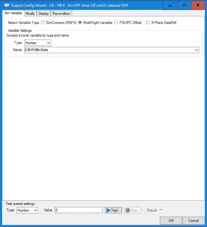
At the first tab – Sim Variable, select Mobi Flight Variable in the first available option, which is Sim Variable Type. Than, a Variable Settings section will appear. Here, select Number in the Type option (maybe it will be pre-selected). For the name, you should be able to select the iCBHR4BtnState variable, since we already defined it in the previous input config. Type it there if not. Than, go to the Display tab.

Here, in Display type section, select Output Device in the Choose option. In Module selection, select the MF_Mega_CB Arduino board. And in the Use Type of select “LED / Output” (the outputs connected to the relay board, that drives the electromagnets, are configured as LED / Output device). The Display settings section should appear unless it already have did that. In the Select Pins select the EM_CB_HR_4, which is the output connected to the relay controlling the respective electromagnet for the fourth circuit breaker in the top row. Than you can switch to Precondition tab.

There should be an “empty item” in the Precondition list. Select it. When you do, the Precondition type and Precondition settings sections should apper below and become editable. In the Use type of in the Precondition type select MobiFlight Variable. In the Precondition settings select or type the iCBHR4BtnState in the Choose variable option. Than set the If current value is to = 0.
This output config is responsible for turning OFF the electromagnet when the physical circuit breaker is “popped-out”, that is, when the electromagnet shaft will stop pressing the respective switch.
You might now think, are you sure? Yes, just bear with me. Later, when I show you how to trigger the electromagnet, you will see that it is not a “momentarily” event. So, the power would be applied to the electromagnet from that moment and would go on – preventing you from pressing the circuit breaker back in, would heat the electromagnet and so. So, once the circuit breaker is “popped-out”, we need to cut power to it’s electromagnet. How does the above output config do it?
We know the button (circuit breaker) state thanks to the previous input config. It is stored in the iCBHR4BtnState MobiFlight variable. It has a value of 1 when the switch is pressed and 0 when it is released. In this output config, we defined it to react on this variable change, on the first Sim Variable tab. Than on Display tab, we told MobiFlight to send the value of that variable as output to the Arduino PIN that controls the electromagnet (0 means OFF, 1 means ON). So far, this output config would react to variable change between both values. But we also defined a precondition that says that iCBHR4BtnState must be 0, which means that the config will be processed only when iCBHR4BtnState = 0, thus only when circuit breaker switch is released, when the circuit breaker “pops-out” (no matter if it was triggered by the sim or manually) and thus the value sent to the electromagnet controlling output PIN will always be 0 (in the case of this config). So it will shut it OFF if it was ON, or it will be like nothing if it was OFF.
The mentioned input and output config is the same for all of the 8 circuit breakers and for all aircraft. Of course they are not exactly the same, the variable name, description, inputs and outputs change respectively.
Programming circuit breakers for the Steam Gauge Overhaul – Analog Bonanza

Before we can continue in creating MobiFlight configs, we first need to identify which circuit breakers that the aircraft simulates we want to link with our physical ones. You might want all of them, but my circuit breakers panel has only 8, so I need to choose just some, since the aircraft will likely have more than that. And than we need to figure out, how they operate.
Inspecting the aircraft circuit breakers


Looking through the aircraft virtual cockpit – discovering the different circuit breakers available and trying out what they do (which ones will cause me the most challenging times when they pop-out causing the related systems to stop working), I decided to interface the following ones with my physical circuit breakers:
| ACC POWER | ANCVS RELAY | A/P CONT | AUD PANEL |
| FLAP MOTOR | LANDING GEAR RELAY | COM 1 | NAV 1 |
Now that we know what circuit breakers we want to interface, the next step is to figure out, how they operate. How we can trigger them – to pop them out and push them back in, without clicking on them.
One road you can take is to study the aircraft model behavior files. For example, the aircraft from Black Square are pretty nicely commented, so it is not that hard to find some information there. Or, surely, you can get some insights by opening the aircraft in the MSFS editor (after enabling Developer tools). But it is some time since I played with that, and it was for scenery … and, both of these are more like “MSFS developer” ways. And really out of scope of this article. So I will try to describe, shortly, the way I did it with FSUIPC.
So, I started MSFS, loaded the desired aircraft, resized the MSFS window to about half of my desktop (so I can see other programs too) and I opened FSUIPC from that “icons hiding place” near the clock in the bottom right corner of main Windows panel.
In FSUIPC, you need to enable logging to console – just click on Log menu and there on Open console. The black console that looks like command line windows should open, but not much will happen in there, unless you check some option in the Log menu to log something. One of the options that is somewhat eye-catching is the Events option.

But you need to be quick with this one. As aircraft usually triggers a lot of events. So, I enabled it and of course the console started filling up with various events rapidly. I than quickly moved cursor to the circuit breaker I wanted to try and clicked it multiple times, sometimes even seeing a different event in the console by the side vision of my eye. Than you have to go fast back to FSUIPC window and disable logging of the Events, which will stop the console output. Now, you have an opportunity to scroll back through the console output looking for “something different”. Most of the logged events will be the same, repeating itself, as they are triggered automatically without any user input. But you most likely will find some else between them. The amount of these should match the times you clicked the circuit breaker, but of course, I never counted it. I just pressed the circuit breaker multiple times to catch the “pattern”, to help me identify the right event.
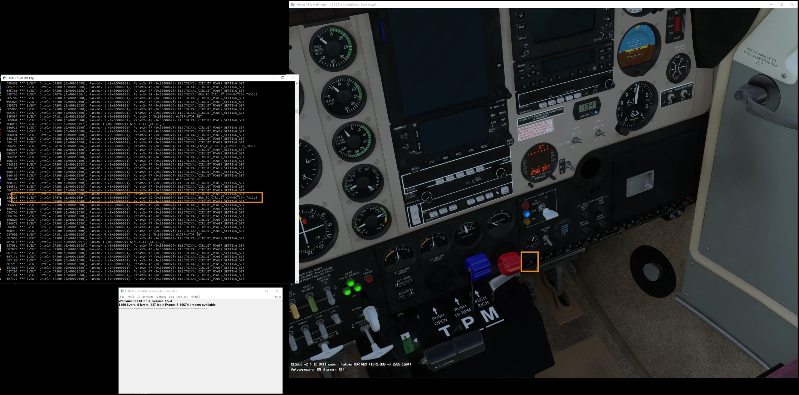
On the picture above you can see that I tried COM 1 circuit breaker. In the console, I highlighted the ELECTRICAL_BUS_TO_CIRCUIT_CONNECTION_TOGGLE event. That is the event triggered by toggling the circuit breaker. And you can see it two more times above between all those same other repeating events. On the highlighted line, notice that it has 2 parameters – Param 1 = 3 and Param 2 = 52. The Param 1 is a source bus index and Param 2 is destination circuit. The ELECTRICAL BUS_TO_CIRCUIT_CONNECTION TOGGLE event is sort of programmatic equivalent for an electrical switch. As it name says, it toggles (connects or disconnects) a circuit to and from a power bus. You can read more about it here. Diving deeper into it is also beyond the scope of this article. Having the event and the params is enough for us, for now.
Let’s look at the second example:

In the picture above, I tried to hunt an event for the ANCY RELAY circuit breaker. And you may notice, this one is driven by different event: ELECTRICAL_BUS_TO_BUS_CONNECTION_TOGGLE. It also has parameters, Param1 = 3 and Param2 = 5. This time they are source and destination bus, because this event connects/disconnects two power buses. But the idea is the same.
After inspecting all the circuit breakers I was interested in like this, I ended up with the following table:
| Circuit breaker | Bus number | Circuit number | Event |
|---|---|---|---|
| ACC POWER | 2 | 21 | ELECTRICAL_BUS_TO_CIRCUIT_CONNECTION_TOGGLE |
| ANCVS RELAY | 3 | 5 | ELECTRICAL_BUS_TO_BUS_CONNECTION_TOGGLE |
| A/P CONT | 3 | 61 | ELECTRICAL_BUS_TO_CIRCUIT_CONNECTION_TOGGLE |
| AUD PANEL | 3 | 49 | ELECTRICAL_BUS_TO_CIRCUIT_CONNECTION_TOGGLE |
| FLAP MOTOR | 4 | 3 | ELECTRICAL_BUS_TO_CIRCUIT_CONNECTION_TOGGLE |
| LANDING GEAR RELAY | 2 | 6 | ELECTRICAL_BUS_TO_CIRCUIT_CONNECTION_TOGGLE |
| COM 1 | 3 | 52 | ELECTRICAL_BUS_TO_CIRCUIT_CONNECTION_TOGGLE |
| NAV 1 | 3 | 56 | ELECTRICAL_BUS_TO_CIRCUIT_CONNECTION_TOGGLE |
Setting up the MobiFlight config for the circuit breaker switch
Let’s start again with the input config. I hope you’ve read the “common programming” chapter above, if not, do so. To recap, we already defined one input config to store the state of circuit breaker switch into MobiFlight variable. But it has no relation to the sim at all. Now, we will tell MobiFlight to “pop-out” aircraft circuit breaker when our physical one “pops-out”, and to “press-it-in” when our physical one does. And here is how it’s done.
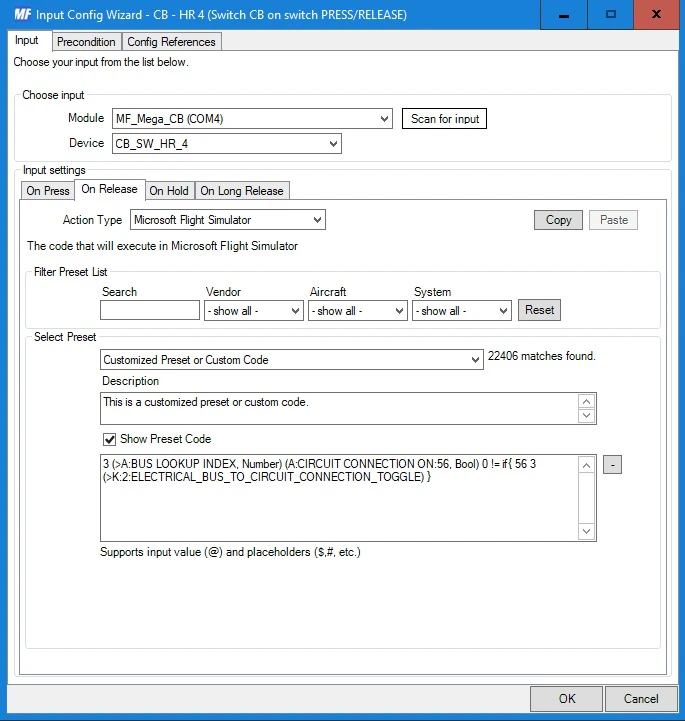
Again, start with new input config at the Input configs tab. I described it as: CB – HR 4 (Switch CB on switch PRESS/RELEASE).

At the first Input tab, select MF_Mega_CB in the Module option, and CB_SW_HR_4 in the Device option. That is the switch mounted on the fourth circuit breaker at the top row of the circuit breaker panel. This is the same as we did for the input config in the “common” programming. But the rest is different. In the On Press tab, select Microsoft Flight Simulator in the Action Type option. Further down, in the Select Preset section, check the Show Preset Code checkbox to display the preset code input text box. Type in (or copy) the following code:
3 (>A:BUS LOOKUP INDEX, Number) (A:CIRCUIT CONNECTION ON:56, Bool) 1 != if{ 56 3 (>K:2:ELECTRICAL_BUS_TO_CIRCUIT_CONNECTION_TOGGLE) }
And now the part where I try to explain it 🙂 I will not explain the syntax, it’s in RPN notation and it even spins my brain around every time I need to write something in it. As it is usually once a half a year, I’m always learning it from the start :/ You can read about the RPN notation here. Now, start with this part:
56 3 (>K:2:ELECTRICAL_BUS_TO_CIRCUIT_CONNECTION_TOGGLE)
The above code is the event we found in previous chapter – Inspecting the aircraft circuit breakers – refer to the table. The event has 2 parameters, which in RPN notation, are written before the call of the event. By the event name and the parameters 56 and 3 you will find, that this event call is for toggling the COM 1 circuit breaker. But because this is a “toggle” event, we cannot just call it in the On Press event of the physical circuit breaker switch. Because than we could find ourselves in the following situation. We push-in the circuit breaker, which will press the switch and trigger the On Press event in MobiFlight, which in turn would trigger the code to toggle the aircraft circuit breaker. But if the circuit breaker in the aircraft was already pressed-in (circuit connected), it will pop-out (disconnect the circuit). This would ultimately unsynchronize our physical circuit breaker with the one in the simulator. That is what the rest of the code takes care of:
3 (>A:BUS LOOKUP INDEX, Number) (A:CIRCUIT CONNECTION ON:56, Bool) 1 != if{ ... }
As mentioned before, what the ELECTRICAL_BUS_TO_CIRCUIT_CONNECTION_TOGGLE event does is, that it actually connects/disconnects a “circuit” to/from a “power bus”. In this case, we press the circuit breaker in, thus we want to connect the circuit to the bus. Because when the circuit breakers in being pressed-in, it is being reset, to restore functionality of devices protected by it. So before we trigger it, we need to test that the actual circuit number – 56 is not connected to the power bus – 3. That is what the above code does. The 3 (>A:BUS LOOKUP INDEX, Number) code looks up the internal simulator bus number for power bus number 3 and stores it to the stack. The (A:CIRCUIT CONNECTION ON:56, Bool) tests “aircraft (A) variable” – whether the given circuit number is on. That check requires the circuit number – 56 and the power bus number – 3 (which it takes from the top of the stack). The 1 != than checks if the result of the check is not 1 (because 1 – true – means the circuit is connected to the bus, 0 means the circuit is not connected to the bus). Thinking of it inverted, it will trigger the toggle when the result of the check is 0 – thus when the circuit is not connected to the bus and we want to connect it back. And what is between if{ and } is a code that is triggered, when the check is true – here the call to trigger the circuit to the bus.
Translated to the human speech, it means: “If circuit number 56 is not connected to bus number 3, trigger the circuit number 56 to bus number 3”.
I hope I managed to somewhat explain it 🙂 Of course, if you came to this as an “unwritten book”, so stuff like “stack”, “aircraft variable” or “event” are completly foreign to you, you will need to do some additional reading from the MSFS SDK.
The same approach is used on the On Release tab:
The Action Type will be again Microsoft Flight Simulator. Below, in the Select Preset section, check the Show Preset Code checkbox to show the preset code input text box and type or copy the following code:
3 (>A:BUS LOOKUP INDEX, Number) (A:CIRCUIT CONNECTION ON:56, Bool) 0 != if{ 56 3 (>K:2:ELECTRICAL_BUS_TO_CIRCUIT_CONNECTION_TOGGLE) }This is almost exactly the same code like we entered on the On Press tab, it only differs by the condition 0 != , which just inverts the logic – testing whether the circuit number 56 is connected to power bus 3 before triggering the event to toggle it and thus disconnecting the circuit 56 from power bus 3.
Setting up the MobiFlight config for the circuit breaker electromagnet
There is one left behavior left to implement and that is to energize the “physical” circuit breaker electromagnet to “pop-out” the circuit breaker in the event the circuit breaker in the simulator “pops-out”.
For this, we add another config to the list at the Output configs MobiFlight tab. I’ve set a description: CB – HR 4 – Em ON when CB switch pressed IN to mine. We still continue on setting up the fourth circuit breaker in the top row of the circuit breaker panel, the one controlling COM 1 for the Bonanza A36 aircraft.

At the first SimVariable tab,select SimConnect (MSFS) for the Select Variable Type option. Then click on the Show Preset Code checkbox in the Select Preset section, as we will again input custom preset code and type or copy the following code:
3 (>A:BUS LOOKUP INDEX, Number) (A:CIRCUIT CONNECTION ON:56, Bool) 0 ==This code written in RPN notation checks whether the circuit number 56 is disconnected from power bus 3. So, this output config will trigger when this is true and that is when the COM 1 circuit breaker “pops-out”. But wouldn’t we trigger that by pulling the “physical” circuit breaker? Well, wait for the Precondition tab.
As you already noticed, this is part of the code, that we enetered to the On Press event of the circuit breaker switch in the Setting up the MobiFlight config for the circuit breaker switch chapter, just the condition is written as 0 == rather than 1 != for better reading. But logically-wise, they are exactly the same conditions.
3 (>A:BUS LOOKUP INDEX, Number) (A:CIRCUIT CONNECTION ON:56, Bool) 1 !=
At Display tab we set the Display type section first. Select Output Device in the Choose option. Than MF_Mega_CB in the Module selection followed by LED / Ouput in the Use type of option.
In the Select Pins, select the EM_CB_HR_4, which is the Arduino output connected to the relay board input controlling the relay connected to the electromagnet of the fourth circuit breaker in the top row of our circuit breaker panel. The value that MobiFlight will set to the output will be 1 (HIGH – 5V), because 1 will be the result of the watched SimConnect preset code defined on the previous Sim Variable tab.

We want to energize the circuit breaker electromagnet only when the circuit breaker “pops-out” due to the event in the simulator, not when pulling out the “physical” one manually. How do we achieve that? Add a precondition where iCBHF4BtnState = 1, which means, that the “physical” circuit breaker switch is pressed so the “physical” circuit breaker is “pushed-in”. This “output setup” now tells MobiFlight “when the circuit breaker switch is pressed-in and circuit number 56 is disconnected from bus 3, energize the electromagnet”. It will make the physical circuit breaker to “pop-out”, triggering On Release event on the switch which in turn triggers another event to de-energize the electromagnet, as described in the The “common ” programming chapter. The electromagnet will not be triggered by manually pulling-out the physical circuit breaker, because in that case, the switch On Release action will trigger, setting iCBHF4BtnState to 0 and also toggling the circuit state in the simulator. This change itself would trigger this output event, but since the iCBHF4BtnState was set to 0, it will not.
Programming circuit breakers for the WB-Sim C172

I have to admit that a lot of MSFS default aircraft are great, but I am from the “hard simmer camp”, so the more the aircraft simulates, like pilot sweating, the more I will like it 🙂 So, in the case of one of the most used training aircraft, I of course grasped for the more advanced than the default one is.
Inspecting the aircraft circuit breakers

Below is a table containing the names of the circuit breakers I decided to interface with my “physical” circuit breakers. The table reflects the “physical” mapping, where the top row is top row in my circuit breaker panel, bottom is the bottom one and the columns represent the respective circuit breakers in each row, 1 to 4, from left to right.
| AUTO PILOT | INST | AVN BUS 1 | AVN BUS 2 |
| TURN COORD | FLAPS | ADF | XPNDR |
and here is the table of found out events / LVars that drive those circuit breakers:
| Circuit breaker | Bus number | Circuit number | Event or LVar |
|---|---|---|---|
| AUTO PILOT | L:C172X_AP_BREAKER_PULLED | ||
| INST | L:C172X_INST_BREAKER_PULLED | ||
| AVN BUS 1 | 1 | 3 | ELECTRICAL_CIRCUIT_TOGGLE |
| AVN BUS 2 | 2 | 4 | ELECTRICAL_CIRCUIT_TOGGLE |
| TURN CORD | L:C172X_TURNCOORD_BREAKER_PULLED | ||
| FLAPS | L:C172X_FLAPS_BREAKER_PULLED | ||
| ADF | L:C172X_ADF_BREAKER_PULLED | ||
| XPNDR | L:C172X_XPNDR_BREAKER_PULLED |
Setting up the MobiFlight configs
I will only shortly describe here some of the “specifics” for this aircraft. Refer to the The “common ” programming chapter, which also applies for this aircraft and to the Programming circuit breakers for the Steam Gauge Overhaul – Analog Bonanza chapter, where you can get more detailed insights and description of the Hows and Whys? of the “MobiFlight programming”.
The WB-Sim Cessna 172 is nice example for us of different approach, way, the aircraft circuit breakers work. When I tried to catch up some events playing around with the aircraft circuit breakers, like I did with the Bonanza A36, I got nothing. So I had to try different approach and that is listing the LVars using FSUIPC, look at what is there, and maybe I’ll might find something circuit breakers related.
And, there it was … if it’s not events, it’s usually LVars 🙂

But I guess you know that since the aircraft “circuit breakers table” was listed before this paragraph, so you know that most of the chosen circuit breakers are controlled by LVars and just the AVN BUS 1 and AVN BUS 2 by events.
The configs for the AUTO PILOT circuit breaker
Let’s look at the code for the HR 1 switch (switch for the first circuit breaker in the top row of our circuit breaker panel) that works with the LVar and controls the AUTO PILOT circuit breaker, first the On Press event:
(L:C172X_AP_BREAKER_PULLED, Bool) 1 == if{ 0 (>L:C172X_AP_BREAKER_PULLED, Bool) }Translating this to plain English, it is “if AP circuit breaker is not pushed-in, push it in”. The push it in part is the 0 (>L:C172X_AP_BREAKER_PULLED, Bool) code, which stores value 0 to the C172X_AP_BREAKER_PULLED local variable (LVar). It will push the circuit breaker in. The condition part is the (L:C172X_AP_BREAKER_PULLED, Bool) 1 == if{ } code. It tests whether the value of the C172X_AP_BREAKER_PULLED is 1, which is when the auto pilot circuit breaker is “popped-out”.
The code for the On Release event is the same just with inverted logic:
(L:C172X_AP_BREAKER_PULLED, Bool) 0 == if{ 1 (>L:C172X_AP_BREAKER_PULLED, Bool) }And the code that is used in the output config that energizes the HR 1 electromagnet, making the physical circuit breaker to “pop-out”, is just the condition part:
(L:C172X_AP_BREAKER_PULLED, Bool) 1 ==The configs for the AVN BUS 1 circuit breaker
Let’s look at the code for the HR 3 switch (switch for the third circuit breaker in the top row of our circuit breaker panel) that works with an event and controls the AVN BUS 1 circuit breaker, but uses slightly different test than in the case of Bonanza A36. The On Press preset code:
1 (>A:BUS LOOKUP INDEX, Number)(A:BUS CONNECTION ON:3, Bool) 1 != if{ 46 (>K:ELECTRICAL_CIRCUIT_TOGGLE) }The logic of the code is the same as in example events shown in the Setting up the MobiFlight config for the circuit breaker switch for Bonanza A36, but surprisingly it did not work checking the A variable: CIRCUIT CONNECTION ON like in Bonanza, even though one would expect it from the ELECTRICAL_CIRCUIT_TOGGLE event. As you can see above, there is used BUS CONNECTION ON aircraft (A) variable in the test condition. In the On Release event, the logic is just reversed.
Programming circuit breakers for the DHC-2 Beaver

To be more specific, for the wonderful DHC-2 Beaver developed by Blackbird Simulations that was added to MSFS in the 40th Anniversary Update. If you know about the flight simulation related posts on my website, you know that DHC-2 is one my favorite aircraft, and it has working circuit breakers, so … 🙂
Inspecting the aircraft circuit breakers

Below is a table containing the names of the circuit breakers I decided to interface with my “physical” circuit breakers. The table reflects the “physical” mapping, where the top row is top row in my circuit breaker panel, bottom is the bottom one and the columns represent the respective circuit breakers in each row, 1 to 4, from left to right.
| COMM/NAV | XPONDER | AP | RADIO RELAY |
| START RELAY | FUEL BOOST PUMP | LANDING LIGHTS | INST LIGHT |
and here is the table of found out events that drive those circuit breakers:
| Circuit breaker | Bus number | Circuit number | Event |
|---|---|---|---|
| COMM/NAV | 4 | 12 | ELECTRICAL_CIRCUIT_BREAKER_TOGGLE |
| XPONDER | 4 | 6 | ELECTRICAL_CIRCUIT_BREAKER_TOGGLE |
| AP | 4 | 14 | ELECTRICAL_CIRCUIT_BREAKER_TOGGLE |
| RADIO RELAY | 4 | 5 | ELECTRICAL_CIRCUIT_BREAKER_TOGGLE |
| 4 | 8 | ||
| 4 | 9 | ||
| 4 | 10 | ||
| 4 | 11 | ||
| START RELAY | 1 | 4 | ELECTRICAL_CIRCUIT_BREAKER_TOGGLE |
| FUEL BOOST PUMP | 3 | 2 | ELECTRICAL_CIRCUIT_BREAKER_TOGGLE |
| LANDING LIGHTS | 3 | 18 | ELECTRICAL_CIRCUIT_BREAKER_TOGGLE |
| INST LIGHT | 3 | 19 | ELECTRICAL_CIRCUIT_BREAKER_TOGGLE |
Setting up the MobiFlight configs
I will only shortly describe here some of the “specifics” for this aircraft. Refer to the The “common ” programming chapter, which also applies for this aircraft and to the Programming circuit breakers for the Steam Gauge Overhaul – Analog Bonanza chapter, where you can get more detailed insights and description of the Hows and Whys? of the “MobiFlight programming”.
The input config for the RADIO RELAY circuit breaker
The DHC-2 Beaver uses another different event for triggering the toggle of the circuit breakers. All of the circuit breakers I’ve chose use the same event – ELECTRICAL_CIRCUIT_BREAKER_TOGGLE. I will show you the code for the RADIO RELAY circuit breaker, which is different and interesting in that it triggers 5 of these events instead of one, like the others do.
The preset code below is for the On Press event of the HR 4 switch (belonging to the fourth physical circuit breaker in the top row), which we are mapping to the RADIO RELAY circuit breaker in the aircraft:
4 (>A:BUS LOOKUP INDEX, Number)
(A:CIRCUIT BREAKER PULLED:5, Bool) 0 != if{ 5 4 (>K:2:ELECTRICAL_CIRCUIT_BREAKER_TOGGLE) }
(A:CIRCUIT BREAKER PULLED:8, Bool) 0 != if{ 8 4 (>K:2:ELECTRICAL_CIRCUIT_BREAKER_TOGGLE) }
(A:CIRCUIT BREAKER PULLED:9, Bool) 0 != if{ 9 4 (>K:2:ELECTRICAL_CIRCUIT_BREAKER_TOGGLE) }
(A:CIRCUIT BREAKER PULLED:10, Bool) 0 != if{ 10 4 (>K:2:ELECTRICAL_CIRCUIT_BREAKER_TOGGLE) }
(A:CIRCUIT BREAKER PULLED:11, Bool) 0 != if{ 11 4 (>K:2:ELECTRICAL_CIRCUIT_BREAKER_TOGGLE) }
I know it might seem longer (which it is) and more complicated (which is not that much). All there is, with other circuit breakers we had one condition and one action, here we have 5 of them.
The good thing is, because of how RPN code works, that we only need to setup the bus number for the tests once: 4 (>A:BUS LOOKUP INDEX, Number) and then all the following conditions use it. Than it is really just a series of conditions -> actions witch changing parameters: (A:CIRCUIT BREAKER PULLED:5, Bool) 0 != if{ 5 4 (>K:2:ELECTRICAL_CIRCUIT_BREAKER_TOGGLE) } . Yes, there is another new aircraft (A) variable: CIRCUIT BREAKER PULLED. So the code checks whether the value of that variable for given circuit breaker – number 5 in this example, is not 0. If it is not 0, it means the circuit breaker is “popped-out” and in that case, we will toggle the circuit breaker to push it in, since that is what is supposed to happen when the circuit breaker switch is pressed.
Note that this code does 5 condition checks and will trigger 5 actions in series. So it is not an “AND” relationship. If due to some other code or bug should it happen that some of those 5 variables will have different values, only those satisfying the conditions will be toggled. But I don’t expect that to happen, at least not in my “cockpit configuration”. It is just that the RADIO RELAY is one circuit breaker that acts as five.
For the On Release, just the condition logic is reversed:
4 (>A:BUS LOOKUP INDEX, Number)
(A:CIRCUIT BREAKER PULLED:5, Bool) 1 != if{ 5 4 (>K:2:ELECTRICAL_CIRCUIT_BREAKER_TOGGLE) }
(A:CIRCUIT BREAKER PULLED:8, Bool) 1 != if{ 8 4 (>K:2:ELECTRICAL_CIRCUIT_BREAKER_TOGGLE) }
(A:CIRCUIT BREAKER PULLED:9, Bool) 1 != if{ 9 4 (>K:2:ELECTRICAL_CIRCUIT_BREAKER_TOGGLE) }
(A:CIRCUIT BREAKER PULLED:10, Bool) 1 != if{ 10 4 (>K:2:ELECTRICAL_CIRCUIT_BREAKER_TOGGLE) }
(A:CIRCUIT BREAKER PULLED:11, Bool) 1 != if{ 11 4 (>K:2:ELECTRICAL_CIRCUIT_BREAKER_TOGGLE) }
The output config for the RADIO RELAY circuit breaker
I will also show a preset code in the output configuration for the RADIO RELAY circuit breaker, which decides whether to energize the circuit breaker electromagnet to “pop-out” the circuit breaker. It is also little different than the ones so far described in this article, because, as you probably noticed in the previous chapter, the RADIO RELAY actually works as 5 circuit breakers. Here we go:
4 (>A:BUS LOOKUP INDEX, Number)
(A:CIRCUIT BREAKER PULLED:5, Bool)
(A:CIRCUIT BREAKER PULLED:8, Bool) *
(A:CIRCUIT BREAKER PULLED:9, Bool) *
(A:CIRCUIT BREAKER PULLED:10, Bool) *
(A:CIRCUIT BREAKER PULLED:11, Bool) *
1 ==
First the code looks-up the internal simulator bus index for bus index 4 and stores it to the top of the stack. That is what this code: 4 (>A:BUS LOOKUP INDEX, Number) does. Than there are five checks of the aircraft (A) variable values: (A:CIRCUIT BREAKER PULLED:5, Bool). Notice the * between the checks. The asterisk is an “AND” operator. So at the end of the check of the five variables, there will be either value 1 on the top of the stack, or 0. 1 will be there only if all the 5 variables has a value of 1. If one or more of them have value of 0, the result will be 0. Then there is the last check: 1 == , which tests if that resulting value is 1. If it is 1, it means that all five circuit breakers hidden behind the RADIO RELAY circuit breaker are “pressed-in” – and so the “physical” circuit breaker may be “popped-out” by the electromagnet. Of course, for that to happen, also the config precondition must be satisfied. If you would like to change the relation to “OR”, so at least one of the five variables must be 1, just change the * to +.
Programming circuit breakers for the Blacksquare Turbine Duke

Turbine (and Piston) Duke were ones of my favorite aircraft in FSX/Prepar3D. They were also ones of the most realistic back at the time and especially turbine version was a challenge for proper engine management. So I was very happy, when they become available for MSFS, developed by Black Square and they are again top-notch. Interfacing their circuit breakers with “physical” ones was of course a must-do thing for me.
Inspecting the aircraft circuit breakers

Below is a table containing the names of the circuit breakers I decided to interface with my “physical” circuit breakers. The table reflects the “physical” mapping, where the top row is top row in my circuit breaker panel, bottom is the bottom one and the columns represent the respective circuit breakers in each row, 1 to 4, from left to right.
| AUTO PLT | ENG INSTR | COM 1 | COM 2 |
| FLAP MOTOR | GEAR MOTOR | WING PUMP L | WING PUMP R |
and here is the table of found out events that drive those circuit breakers:
| Circuit breaker | Bus number | Circuit number | Event |
|---|---|---|---|
| AUTO PLT | 8 | 51 | ELECTRICAL_BUS_TO_CIRCUIT_CONNECTION_TOGGLE |
| ENG INSTR | 8 | 49 | ELECTRICAL_BUS_TO_CIRCUIT_CONNECTION_TOGGLE |
| COM 1 | 10 | 69 | ELECTRICAL_BUS_TO_CIRCUIT_CONNECTION_TOGGLE |
| COM 2 | 11 | 73 | ELECTRICAL_BUS_TO_CIRCUIT_CONNECTION_TOGGLE |
| FLAP MOTOR | 7 | 13 | ELECTRICAL_BUS_TO_CIRCUIT_CONNECTION_TOGGLE |
| GEAR MOTOR | 9 | 14 | ELECTRICAL_BUS_TO_CIRCUIT_CONNECTION_TOGGLE |
| WING PUMP L | 3 | 58 | ELECTRICAL_BUS_TO_CIRCUIT_CONNECTION_TOGGLE |
| WING PUMP R | 4 | 59 | ELECTRICAL_BUS_TO_CIRCUIT_CONNECTION_TOGGLE |
Setting up the MobiFlight configs
I will only shortly describe here some of the “specifics” for this aircraft. Refer to the The “common ” programming chapter, which also applies for this aircraft and to the Programming circuit breakers for the Steam Gauge Overhaul – Analog Bonanza chapter, where you can get more detailed insights and description of the Hows and Whys? of the “MobiFlight programming”.
Since the Turbine Duke was developed by Black Square, I kind of expected the circuit breakers will work the same, or very similar way, they do in the Steam Gauge Overhaul – Analog Bonanza (since they developed it too). And I was right. In that way, they work the same, using the ELECTRICAL_BUS_TO_CIRCUIT_CONNECTION_TOGGLE event. So the only thing that is different here apart from the Bonanza, are of course used bus numbers and circuit numbers 🙂
Just to recap, this is for example the event On Press preset code for the AUTO PLT circuit breaker switch:
8 (>A:BUS LOOKUP INDEX, Number) (A:CIRCUIT CONNECTION ON:51, Bool) 1 != if{ 51 8 (>K:2:ELECTRICAL_BUS_TO_CIRCUIT_CONNECTION_TOGGLE) }and for the On Release:
8 (>A:BUS LOOKUP INDEX, Number) (A:CIRCUIT CONNECTION ON:51, Bool) 0 != if{ 51 8 (>K:2:ELECTRICAL_BUS_TO_CIRCUIT_CONNECTION_TOGGLE) }In the table above you can see that all of the chosen circuit breakers use the ELECTRICAL_BUS_TO_CIRCUIT_CONNECTION_TOGGLE event. So really the hardest thing here, while setting up the MobiFlight configs, is not to mistype the bus and/or circuit numbers.
Downloads
Below you can download an archive my modified circuit breaker body, the panels as well as the source project(s) to further modify them. Another download contains MobiFlight programming files.
Links
Let’s start with the links to the source files….
- Video-tutorial to build the Triggerable Circuit Braker from Captain Bob
- Captain’s Bob Website
- Captain’s Bob Cessna 172 project on Github
- Captain’s Bob source files for the Triggerable Circuit Braker on Github
And some links to used parts:
- Arduino Mega2560
- 8x ZHK-0735 DC 12V DC Solenoid Electromagnet Self-holding Suction Push-Pull Type
- 8x KW11-3Z Sensitive Microswitch Endstop Limit Switch
- 8 channel 5V Relay Module with LED signaling
And used software:
- Autodesk Fusion
- MobiFlight
- Microsoft Flight Simulator 2020
- FSUIPC
- Steam Gauge Overhaul – Analog Bonanza
- Black Square – Turbine Duke
- Blackbird Simulations DHC-2 Beaver – part of MSFS since 40th Anniversary updatu
- WB-Sim C172 – no longer available for purchase
Related reading
In case you missed it, maybe you would like to dive into some articles from the stage 1 of building my flight simulator cockpit…