A few words for the introduction
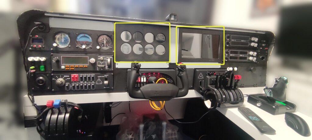
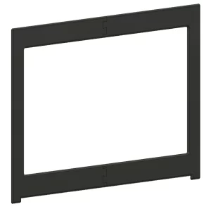
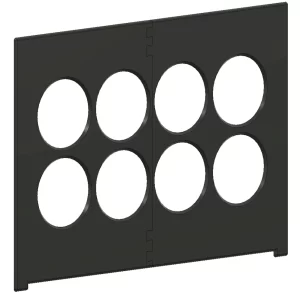
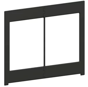
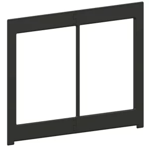
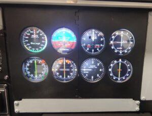
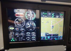
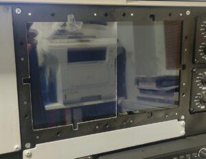
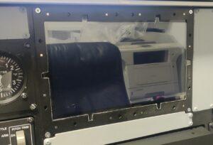
I’ve designed the things around the PFD and MFD, i.e. those two touch screens, by myself for my own use. From the very beginning, I had the goal of making cover frames with different cut-outs (for round, square and other types of instruments), to cover displays and thus simulate the instrument panels of various airplanes. I originally wanted to cut them out of chipboard, but as with the instrument panel, I reconsidered. With a 3D printer, the result will be much more accurate and nicer. It also allowed me to make these panels “snap” and thus easier to replace. If I were to cut them out of chipboard, I’d probably have to re-screw them every time I would want to switch them.
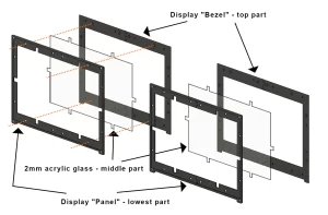
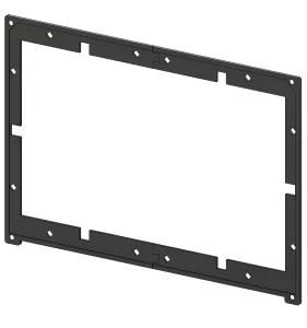
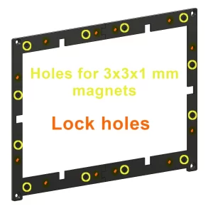
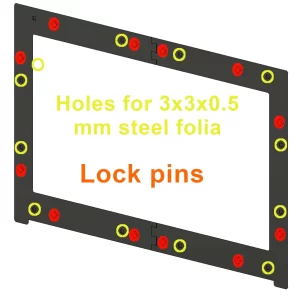
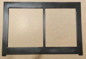
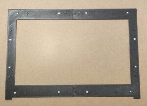
The panels therefore consist of two parts. The first is the panel around the displays, which I have firmly screwed into the cockpit / main panel. On the one hand, these panels cover the displays that slightly protrude over the edge of the main cockpit panel, and on the other hand, they cover the not-so-precise cut-out of the display holes in the main panel. The panels contain small neodymium magnets and moldings for snapping the top bezels (marked in yellow in the gallery). These panels are almost the same for both the PFD and the MFD. In my case, the position of the corner mounting holes for the screws is only slightly different… I designed the panels only after I have had cut out the chipboard prototypes and drilled the mounting holes in the main panel… so I had to adjust the 3D design of these frames and panels accordingly, because it would not be possible to drill another holes in the main panel a millimeter and a half next to the existing ones.
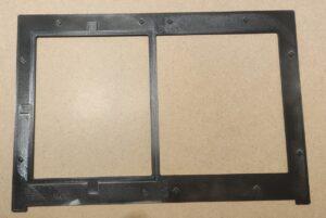
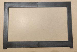
The second part are the upper frames (bezels). They have corresponding moldings for snapping into the lower panels (marked in orange in the gallery) and in the corresponding places also small depressions for sticking the self-adhesive metal foil. Those will meet the neodymium magnets in the lower panels and somehow help the adhesion and the overall connection.
Software for the “gauges”
As for the software side of the PFD and MFD screens, I use quite a few of them. For now, I have the cockpit operational mainly with Flight Simulator 2020. With it, I use the MSFS Pop Out Panel Manager for some aircraft, which allows you to automate the opening of the aircraft avionics displays in separate windows and on defined monitors. I use it for Garmin G1000 avionics PFD and MFD and Boeing 737 and Airbus A320 PFD, ND and other screens.
For “analog gauges” I use Air Manager – which is a software that also allows you to build a panel with instruments for a large number of aircraft. The flight instruments are therefore “drawn” on the monitor, it has nothing to do with the physical ones. Some panels are already ready-made. The software also includes more advanced flight instruments, not just analog ones. If the one you need is not there, you can programm it. And most importantly, saved panels can automatically switch depending on which plane you are currently flying.
I already mentioned the frame for the GTN750 among the display frames. To simulate this navigation unit, I use TDS GTNXi Pro for Flight Simulator, which is based on Garmin Trainer training software for these avionics. So it’s probably the most accurate Garmin GTN 750 simulation you can get for Flight Simulator. I resisted it for a long time because it was impossible to update the navigation database. But this restriction fell and … and that was it 🙂
Gallery
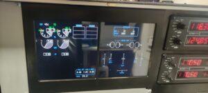
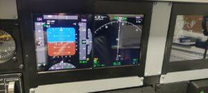
A few pictures that will hopefully make it a little clearer what I’m writing about above, what panels and frames (bezels) and how everything fits together:
Wiring
There’s not much to wire here… just HDMI cables from monitors to PC, monitor power, USB connection for touch screen function… Every connector is different and it’s almost impossible to connect it wrong, so I’ll leave it without hesitation to your own skills : )
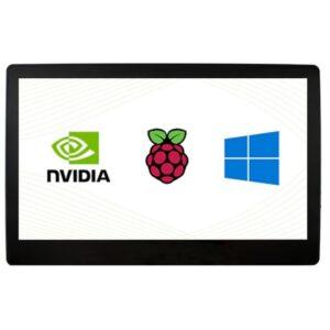
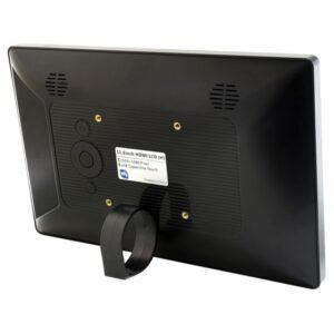
Below is a gallery with used parts… hopefully they will help you find alternatives, when in a few months the links below will no longer be valid 🙁
Downloads
Below, in the first archive, you will find projects for Autodesk Fusion with my panels for displays and of course also STL files for printing:
And in another archive the frames (bezels) for these panels, of course also with the source project (it is actually the same as for the panels) and STL files:
Links
Used material and parts:
- 11.6inch Capacitive Touch Screen LCD with Case, 1920×1080, HDMI, IPS, Optical Bonding Screen, Various Systems Support
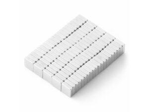
- Neodymium magnet prism 3x3x1 mm, N50, nickel-plated (12 for one frame)
- Flexible metal foil, self-adhesive white, rewritable – from this I cut out 3x3mm squares to stick on the display bezels (12 squares per bezel)
- Hobby plexiglass, 2mm thick – I used it to cut out the cover glass of the displays
And used software:

