

Here we are, the final chapter. Here we will make the “enclosure” for the Prusa MK4S 3D printer actually do something. Well, it already does the main thing it is supposed to do – enclosures the printer. But the added bells and whistles,like temperature sensors, gas sensor and maybe one more stuff does not have any work so far.
We need to tell these components what to do, which, in other words, means, we have to program it. As described in previous chapters, the control board I chose is Arduino UNO, so the programming language will be – C++.
Note that this chapter expects that you know something about programming, programming with Arduino and with C++ as it is really not in the scope of this “post/article” to dive into that too. Neither is a full description of the source code. You will have to bite through it yourself, if you really want to get to know it. I will only describe here the foundations – what the code does, what it should do, does not do yet etc…
What it is supposed to do?
Now about the subject of what the code does … what I wanted it to do from the beginning. We wired some temperature sensors, gas sensor, ventilation fan, control panel in previous chapter. All of these together can do pretty lot of things.
The main interface between these components and us, humans, is the control panel. It has 16×2 character display, a red LED diode, speaker and rotatory encoder with a push-button.
The encoder and the push-button is then the really only option for us to make some inputs to the system. I chose the same logic that also Prusa (but not only they) printers control panel use. Rotating the encoder, we will list through menus (options) and change values. The push-button will be used to accept changes and enter menus.
The control panel works in two modes. The first one, lets call it information mode, will display system information, like inside temperature, outside temperature, gas sensor reading, ventilation fan speed and values of some system settings. That is lot of information for 16×2 display, so they are displayed in “pages”, that are “rotated through” either manually by rotating the encoder, or automatically after passing defined time.
When pressing the push-button when in this information mode, the control panel (display), will switch to “setup” mode. In this mode, we can list through various system settings using the encoder. Again, in sort of “pages”, where each displays the given option with current value. If no input is made with the encoder or push-button for a certain amount of time (like 5s), the system switches back to information mode.
To change the value of any option while in setup mode, we press the push-button again to enter “option change” mode. Than we can change the value of the option by rotating the encoder. To save the value, we push the encoder push-button. It will save the change and will go back to “setup” mode, where we can list through another setting options. The system will also go back from “option change” mode to “setup” mode if no input is made with the encoder for some time.
The “setup”
Imports, constants, other classes – the foundations
Let’s take a look at some parts of the main file – Mouseviator_MK4S_Control_System.ino:
#include <Arduino.h>
#include <LiquidCrystal_I2C.h>
#include <RotaryEncoder.h>
#include <Wire.h>
#include <avr/wdt.h>  // For AVR-based boards
#include "common.h"
#include "DHTAsyncSensors.h"
#include "FireWatch.h"
#include "LCD1602Helper.h"
#include "VentilationControl.h"
#include "MQ2GasSensorNonBlocking.h"
#include "SettingsManager.h"
#include "InfoDisplay.h"
#include "UnoPWM.h"
#include "Utils.h"
//#include <util/atomic.h>

// C++ code
//
//I2C initialization
LiquidCrystal_I2C lcd(0x27, 16, 2);
LCD1602Helper lcdHelper(&lcd); //lcd helper has some nice methods to use when doing output to I2C LCD
UnoPWM pwmController(25000); // 25kHz PWM frequency

#define DHT_SENSOR_TYPE_INSIDE DHT_TYPE_22
#define DHT_SENSOR_TYPE_OUTSIDE DHT_TYPE_11

//Definition of PINS
// Rotary Encoder Pins
constexpr byte gasSensAPIN = (byte) A0;        //pin for MQ2 analog output
constexpr byte encoderS1PIN = (byte) A1;
constexpr byte encoderS2PIN = (byte) A2;
constexpr byte fanRPMPIN = (byte) 2;       //pin for reading FAN RPM
constexpr byte gasSensDPIN = (byte) 3;         //pin for MQQ2 digital ouput
constexpr byte insideTempSensPIN = (byte) 4;     //pin for inside DHT22 sensor
constexpr byte ledPWMPIN = (byte) 5; //pin to drive MOSFET by PWM which controls LED stripe
constexpr byte encoderButtonPIN = (byte) 6;      // pin of encoder button
constexpr byte outsideTempSensPIN = (byte) 7;    //pin for outside DHT11 sensor
constexpr byte buzzerPIN = (byte) 8;           //pin for buzzer
constexpr byte fanPWMControlPIN = UnoPWM::PWM_PIN1;    // 25Khz PWM for FAN
constexpr byte statusLEDPIN = (byte) 10;		//pin for status led
constexpr byte fanDoorServoPIN = (byte)11; //pin for fan door servo, pin 11 is on Timer 2
constexpr byte fanPowerRelayPIN = (byte) 12;
constexpr byte powerRelayPIN = (byte) 13;    //relay to switch ON/OFF printer power

// Rotary Encoder
RotaryEncoder encoder(encoderS1PIN, encoderS2PIN, RotaryEncoder::LatchMode::TWO03);
// SettingsManager Instance
SettingsManager settingsManager(&encoder, &lcdHelper, encoderButtonPIN);

//MQ2 Gas Sensor
MQ2GasSensorNonBlocking gasSensor(gasSensAPIN, gasSensDPIN, &lcdHelper);

//DHT temp/humidity sensors
DHTAsyncSensors dhtSensors(insideTempSensPIN, DHT_SENSOR_TYPE_INSIDE, outsideTempSensPIN, DHT_SENSOR_TYPE_OUTSIDE, DEFAULT_MEASUREMENT_INTERVAL,
		DEFAULT_MEASUREMENT_INTERVAL);

//Create FireWatch object
FireWatch fireWatch(&dhtSensors, &settingsManager, &gasSensor, &lcdHelper, powerRelayPIN, buzzerPIN, statusLEDPIN);

//Create ventilation control object
VentilationControl ventControl(fanDoorServoPIN, fanPWMControlPIN, fanPowerRelayPIN, fanRPMPIN, &pwmController, &fireWatch);

InfoDisplay infoDisplay(&ventControl, &fireWatch, &lcdHelper, &encoder, DEFAULT_INFO_PAGE_DISPLAY_TIME);

//whether wdt is enabled or not
bool wdt_enabled = false;
Apart from standard LiquidCrystal_I2C declaration, there are definitions of constants, mostly for defining what is connected to what PIN on the Arduino. Than we are creating here an instances of helper/functional classes that were written for this and not only for this project 🙂 Most of them I will also try to briefly shed the light on in the below sections. You can see that these classes are initialized with references to various defined Arduino PIN numbers and other classes, so it is all also pretty cross-wired. There are also a lot of constants and macros defined in the “common.h” file (used by almost all classes I think), so take a look at that too.
Speaking of PIN declarations…
Arduino UNO PIN assignments
Most PIN assignments were not chosen randomly, but because they had to be used, or because there were no others left that could be used… Let’s see:
| Pin | Arduino Name | Function | Notes |
|---|---|---|---|
| A0 | Analog 0 | MQ2 gas sensor – analog output | Analog input |
| A1 | Analog 1 | Rotary encoder – channel A | Analog input |
| A2 | Analog 2 | Rotary encoder – channel B | Analog input |
| 2 | D2 | Fan RPM (tachometer) | External interrupt |
| 3 | D3 | MQ2 gas sensor – digital output | External interrupt |
| 4 | D4 | Inside temperature sensor (DHT22) | Single-wire data |
| 5 | D5 | LED strip MOSFET PWM | Timer0 PWM |
| 6 | D6 | Rotary encoder button | Digital input |
| 7 | D7 | Outside temperature sensor (DHT11) | Single-wire data |
| 8 | D8 | Buzzer | Digital output |
| 9 | D9 | PC fan PWM (25 kHz) | Timer1 – custom PWM |
| 10 | D10 | Status LED | Digital output |
| 11 | D11 | Fan door servo | Timer2 – WiderServoTimer2 |
| 12 | D12 | Fan power relay | Digital output |
| 13 | D13 | Printer power relay | Digital output + onboard LED |
The ATmega328P (Arduino UNO) has three hardware timers, each with specific capabilities and PIN mappings:
| Timer | Type | Used by Arduino | PWM Pins |
|---|---|---|---|
| Timer0 | 8-bit | millis(), delay() | D5, D6 |
| Timer1 | 16-bit | Servo library (default) | D9, D10 |
| Timer2 | 8-bit | Free by default | D3, D11 |
Why were the Timers modified?
Timer1 – PC Fan Control (25 kHz PWM). We are using Timer1 to generate a 25 kHz PWM signal for a PC fan, following the approach described here. The reasons, are that:
- Standard analogWrite() PWM (~490 Hz) is not compatible with PC fans
- PC fans require 25 kHz PWM, open-collector style
- Timer1 (16-bit) is the only timer precise enough for this
As a consequence, the standard Servo library cannot be used (we would use it to control the servo that controls the fan doors), because it also relies on Timer1.
That is, why we use slightly modified version of ServoTimer2 library. Ours will be called WiderServoTimer2. Since Timer1 is unavailable, servo control must be moved elsewhere and the only timer left in Arduino UNO is Timer2. So we use it, since:
- It is independent of Timer1
- Can generate accurate servo pulses using interrupts
- We can control servo on pin 11
However, I’d like to note that Timer2 PWM (hardware) on pins D3 and D11 is disabled. That does not mean that we cannot use these PINs for PWM output. It just means that we can’t use analogWrite() for that, because it is disabled by those changes. We are using software generated pulses (that use digitalWrite()).
I know it might seem confusing and it is not in the scope of this article to go deeper inside this, as this is pretty low level stuff. So just take it as it is or you need to dive deep into Arduino documentation by yourself. This turned out to be the only way to go with Arduino UNO for this project.
Timer0 remains unchanged, so:
millis()delay()- time-based logic
- button debouncing
- encoder timing
…all continue to function correctly, which is very important!
The asymmetric reading of temperature/humidity DHT sensor values and MQ2 Gas sensor
The classic Arduino DHT library (e.g., DHT.h) performs blocking sensor reads, meaning it holds up the CPU and disables interrupts while waiting for the DHT sensor to complete its handshake and data transmission. In a project like this one — with high-frequency PWM (25 kHz) for the PC fan, servo timing driven by Timer2, multiple interrupt sources (fan tachometer, gas sensor digital read) and non-blocking control loops — blocking operations can cause timing conflicts, missed pulses, jitter, or lockups. That is why we use our DHTAsyncSensors helper class which uses the DHT-Async library. This library is designed to read DHT sensors in a non-blocking, state-machine fashion, allowing the sketch to continue running other time-critical tasks (like PWM updates and interrupt processing) while the DHT communication proceeds. This results in more reliable temperature and humidity readings in a highly interrupt-driven environment where precise timing must be maintained.
For the same reason, there is a class called MQ2GasSensorNonBlocking, which reads values of gas sensor, also in asynchronous way that allows for minimal delay of the main loop.
The setup() function
And below is the one the of two core functions of each Arduino project, the setup() function:
/**
 * Init function
 */
void setup() {
	//debug init, will init Serial.begin if DEBUG is defined
	DEBUG_INIT(9600);

	//init display
	lcd.init();
	lcd.backlight();
	lcd.display();

	//first init settings manager so stored variables are loaded
	settingsManager.init();

	// --- Add here ---
	delay(2000);  // Allow DHT11/DHT22 to stabilize before any reads / anything happens
	// ---------------

    // Strong pull-ups to stabilize signal lines
    pinMode(insideTempSensPIN, INPUT_PULLUP);
    pinMode(outsideTempSensPIN, INPUT_PULLUP);
    digitalWrite(outsideTempSensPIN, HIGH);

    pinMode(ledPWMPIN, OUTPUT);

	//this will configure pins for gas sensor and attach interrupt to pin where gas sensor digital pin is connected
	//will trigger the function when input changes from 1 to 0
	gasSensor.attach();
	gasSensor.onDigitalInputTriggered(onGasDetected);		//set callback
	gasSensor.setSensorWarmupTime(settingsManager.getGasSensWarmupTime());

	//initialize ventilation control
	ventControl.attachServo();
	ventControl.setMaxInsideTemp((float)settingsManager.getMaxInsideTemp());
	ventControl.setMaxTempDifference((float)settingsManager.getMaxTempDifference());

	//setup PWM controller timer, it will setup pin 9 and 10 for 25kHz output
	pwmController.setupTimer();
    //DEBUG_PRINTLN_F(F("tcn1T: %d"), pwmController.getTcnt1Top());
  	//DEBUG_PRINTLN_F(F("tcn2T: %d"), pwmController.getTcnt2Top());
	//configure fan speed reading
	ventControl.attachFanInterrupt();

	//turn LEDs off
	analogWrite(ledPWMPIN, 0);

	//attach fire watch
	fireWatch.attach();

	infoDisplay.init();
	//reset info page display time to stored value
	infoDisplay.setInfoPageDisplayTime((unsigned long)settingsManager.getInfoDisplaySpeed() * MULTIPLIER_1000);

	// Other Settings Manager init
	settingsManager.onVariableChanged(onVariableChanged);

	settingsManager.handleEncoderInput(); // Initial input check to load settings

	//enable power to power relay
	fireWatch.checkStoredFireAlarm();


}
Logging and debugging
The very first command initializes the debugging and logging. The DEBUG_INIT macro inits a serial output to console, which is used to output log messages. Logging is done by couple of another macros, that you will easily recognize, because they are all starting with DEBUG_PRINT and than something. They are all defined in the “common.h” file, where the debugging can be also globally turned on / off at this line:
#define MK4SC_DEBUG // Comment this line to disable debuggingNote that the calls of the logging macros are mostly commented out throughout the code, because the whole “firmare” is hitting the memory limits of Arduino UNO and there is simply not enough memory to keep them all on. So in the final stages of development, I had to only turn on the one(s) I needed for debugging 🙂
Sketch uses 31934 bytes (99%) of program storage space. Maximum is 32256 bytes.
Global variables use 1576 bytes (76%) of dynamic memory, leaving 472 bytes for local variables. Maximum is 2048 bytes.
The above is the output of Arduino IDE after compiling the whole project – it really uses almost all of the available program memory on Arduino UNO.
The remaing initialization
After the init of debugging, we init the LCD display and than the Settings Manager. The settings manager will read stored settings from Arduino EEPROM, which we want to have as soon as possible, so the values are available for another classes.
Than there is a setup of PIN mode for the inside and outside sensor temperature plus writing an initial value to outside temperature sensor. This should not be needed, as the PINs are initialized with the creation of DHTAsyncSensors class, but there is a strange bug that the outside DHT11 sensor does not return correct data until the rotatory encoder push-button is not pressed at least once. This was to try to help with that, does not change a thing, but does not harm either, so I did not remove it yet.
Next we initialize the PIN for the LED stripe PWM output, initialize the gas sensor, ventilation control and restore some options from the settings. Turn off the LED stripe,
initialize Fire watch class and Info display. Attach the callback for settings manager variable change and check stored fire alarm. Because if last shutdown was due to a fire alarm, the power relay that powers the printer, will not be triggered on until the fire alarm is manually cleared using the control panel.
There are two functions that are referenced in the initiazation code and that are defined in the main .ino file. They are both “event callback” functions.
gasSensor.onDigitalInputTriggered(onGasDetected);The onGasDetected callback function should be called when the MQ2 gas sensor digital input senses gas.
// Other Settings Manager init settingsManager.onVariableChanged(onVariableChanged);And the onVariableChanged will be called when user changes value of any setting via the control panel, giving the info about what was changed and what is the new value.
Function – onGasDetected()
The digital output of the MQ2 gas sensor should trigger the event only when the preset threshold of gas concentration is sensed (set physically via potentiometer on the board). When this happens, we just pass it to the FireWatch class telling it to trigger fire alarm and thus respective consequencing actions.
/**
 * This function will be called when gas sensor digital output is triggered
 *
 * Have to be careful here as this is code that can run in different thread than the main loop
 */
void onGasDetected() {
	//just set the variable here and deal with it in the functions that are called from within the loop so that we're safe
	//from all the hassle that thus function will be called from function that is being called from interrupt, thus from "interrupt" and
	//thus may be processed along the main code with unexpected behavior if we call other stuff from there
	//bFireHazardDetected is bool and thus writing value to it is atomic
	fireWatch.setAlertMode(FireAlertMode::FIRE_HAZARD, false);
}
Function – onVariableChanged()
This functions is used when value of some setting is changed by the user using the control panel, to inform and trigger respective actions in other classes and/or code.
/**
 * This function will be called when some variable is changed using SettingsManager
 */
void onVariableChanged(byte variable, byte newValue) {
	switch (variable) {
	case SettingsManager::VAR_LED_ON:
		//just react to OFF, the other changes will be handled by controlLighting function called from loop
		if (newValue == LIGHT_LED_OFF) {
			//turn LED light off
			analogWrite(ledPWMPIN, LOW);
		}
		break;
	case SettingsManager::VAR_FIRE_ALERT_MODE:
		//If On, it should not be caused by sensors, but by user input
		//switch the value of bFireHazardDetected
		//and let the doFireProtectionCheck() handle the rest
		fireWatch.setAlertMode(static_cast<FireAlertMode>(newValue), (newValue == FireAlertMode::NORMAL) ? false : true);

		//if OFF then we can turn on the power relay
		fireWatch.switchPowerRelayOn();
		break;
	case SettingsManager::VAR_PWR_RELAY_OVERRIDE:
		if (newValue == PWR_RELAY_OVERRIDE_ON) {
			//make sure power is forced on
			fireWatch.switchPowerRelayOn();
		}
		break;
	case SettingsManager::VAR_MAX_TEMP_INSIDE:
		ventControl.setMaxInsideTemp((float)newValue);
		break;
	case SettingsManager::VAR_MAX_TEMP_DIFFERENCE:
		ventControl.setMaxTempDifference((float)newValue);
		break;
	case SettingsManager::VAR_INFO_DISPLAY_SPEED:
		infoDisplay.setInfoPageDisplayTime((unsigned long)newValue * MULTIPLIER_1000);
		break;
	default:
		break;
	}
}
The code handles just some variables changes. Many classes hold reference to the SettingsManager class and thus can detect a change in variable themselves. But some variable changes are handled via this function. Like the change of fire alert mode. The user can change fire alert mode via the control panel – to test the system. In that case, we have to tell FireWatch class and toggle the power relay. The code also forces the power relay on if “override” is active and informs VentilationControl class that the value of max inside temperature or max temperature difference changed. It also tells InfoDisplay class when the value of time to display page changes.
The “main loop”
Below is the code of the second crucial function of every Arduino project, the function that does the main loop:
/**
 * Main loop
 */
void loop() {
	//check WATCH DOG TMER
	check_wdt();

	//calibrate gas sensor
	byte gasSensState = gasSensor.calibrateGasSensor();
	//if calibrating right now, skip everything else
	if (gasSensState == MQ2GasSensorNonBlocking::SENSOR_STATE_CALIBRATING) {
		return;
	}

	// Continuously check encoder input
	//encoder.tick(); // Update encoder state, encoder is used by settings manager and info display
	settingsManager.handleEncoderInput();

	//read sensors
	readSensorValues();

	//do ventilation control
	ventControl.controlVentilation();

	//do fire watch protection
	fireWatch.doFireWatch();

	controlLighting();

	//make sure setup has priority so other code does not kick us out of setup
	if (settingsManager.isSetupOff()) {

		if (!fireWatch.getAlertMode() != FireAlertMode::FIRE_HAZARD) {
			//lastly, display info on LCD
			infoDisplay.displayInfoPage();
		}
	}
}
It actually does not seem that complicated, does it? It is not, unless you start to dig into the called functions … and another functions from there, and class files … going deeper down the basement it might start to get a little confusing.
But have no fear, you will get to the bottom of it, one piece of code at a time.
The first line calls the check_wdt() function. This function is defined within the main .ino file.
In the following code:
//calibrate gas sensor
	byte gasSensState = gasSensor.calibrateGasSensor();
	//if calibrating right now, skip everything else
	if (gasSensState == MQ2GasSensorNonBlocking::SENSOR_STATE_CALIBRATING) {
		return;
	}
we call the function to calibrate the gas sensor. If the sensor is calibrating, we will skip the rest of the code in the main loop until the sensor is calibrated.
Next we call the Settings manager so that it checks whether the user made some input via the rotatory encoder or the push-button and thus whether the user wants to change something. That is the following code:
// Continuously check encoder input
	//encoder.tick(); // Update encoder state, encoder is used by settings manager and info display
	settingsManager.handleEncoderInput();
next, the values of the sensors are read:
//read sensors
	readSensorValues();
The readSensorValues() function is also defined within the main .ino file.
Then, in the main loop is code to perform the ventilation control logic, fire watch logic and to control the LED stripe lighting. It is the following 3 lines:
//do ventilation control
ventControl.controlVentilation();

//do fire watch protection
fireWatch.doFireWatch();

controlLighting();
The last piece of code in the main loop is responsible for displaying the information on the 16×2 LCD panel on the control panel. It does that using the Info Display helper class, but only if the control panel is not in the “setup” mode:
//make sure setup has priority so other code does not kick us out of setup
	if (settingsManager.isSetupOff()) {

		if (!fireWatch.getAlertMode() != FireAlertMode::FIRE_HAZARD) {
			//lastly, display info on LCD
			infoDisplay.displayInfoPage();
		}
	}
Function – check_wdt()
A watchdog timer in Arduino is a feature that helps prevent the system from hanging by automatically resetting the board if it becomes unresponsive. It works by requiring periodic resets from the software. If the reset does not occur within a specified time, the watchdog will reset the Arduino. Our check_wdt() function:
/**
 * This functions checks if WDT should be enabled and enables it if it is not, disabled if should be disabled and resets each time called when enabled
 * It only has effect after gas sensor is calibrated
 */
void check_wdt() {
	if (gasSensor.isSensorCalibrated()) {
		byte enable_wdt = settingsManager.getEnableWDT();
		//if WDT should be enabled, enable it
		if (enable_wdt == WDT_ON && !wdt_enabled) {
			wdt_enable(WDTO_2S);
			wdt_enabled = true;
		} else if (enable_wdt == WDT_OFF && wdt_enabled) {
			//o if should be disabled?
			wdt_disable();
			wdt_enabled = false;
		}

		//if enabled, reset..
		if (wdt_enabled) {
			wdt_reset();
		}
	}
}
does exactly that with some added checks. First, it only works after gas sensor is calibrated, because the calibration could easily make the watch dog timer think the board is frozen even when it is not. This feature also must be enabled by the settings via the control panel.
Function – readSensorValues()
/**
 * Reads values of all sensors
 *
 */
void readSensorValues() {
	//read values from inside temperature/humidity sensor
	dhtSensors.measureInsideEnvironment();

	//read values from outside temperature/humidity sensor
	dhtSensors.measureOutsideEnvironment();

	//measure gas sensor resistance
	if (gasSensor.isSensorCalibrated()) {
		//measure the resistance
		gasSensor.measureSensorResistance();
	}
}
Is not overly complicated. It just calls the respective classes to do the actual job.
Function – controlLighting()
The function that controls the LED stripe lighting is simple. It just writes the required PWM output to the respective output PIN. The added functionality here is that it waits for defined time – LED_ON_DELAY before the first attempt to write the output is made. This is due to limit power spikes if this would be triggered right after booting the board when the electrons might not be completely stabilized throughout our circuits.
void controlLighting() {
	//if LED should be ON and we are running sufficiently long
	if (settingsManager.getLEDOn() == LIGHT_LED_ON && (millis() >= LED_ON_DELAY)) {
		//write LED PWM output, it comes in percent from settings manager,	need to re-map it to 255
		byte ledPWMValue = settingsManager.getLEDPWM();

		analogWrite(ledPWMPIN, map(ledPWMValue, 0, 100, 0, 255));
	} else {
		//light should be off
		analogWrite(ledPWMPIN, LOW);
	}
}
Note that LED stripe PWM uses PIN 5, which uses Timer 0 and thus (with PIN 6) is the only unmodified PWM output in this project. Read more in: why timers were modified.
Settings Manager
- Header file: SettingsManager.h
- Cpp file: SettingsManager.cpp
The SettingManager class handles the functionality of displaying and changing setting variables values. It also loads the values of these settings stored in EEPROM and saves them there and contains functions to retrieve the values for other classes/code to use.
Currently, 17 setting “variables” can be changed. They are all of “byte” type (as this is the only type that EEPROM API supports) and are stored in a byte array, accessed by an index. In total, there is 18 variables that the class works with (one is read-only).
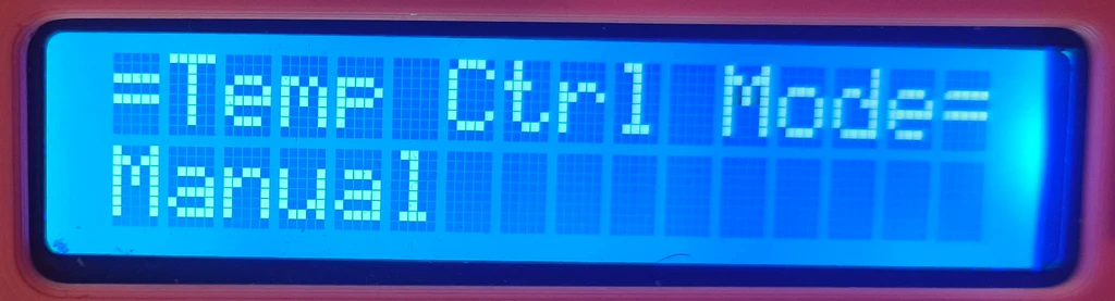
| Index name: | VAR_TEMP_CONTROL_MODE |
| Index value: | 0 |
| Possible value: | 0 = AUTO_MODE 1 = MANUAL_MODE |
| Description: | Temperature control mode, auto or manual |
| Index name: | VAR_MAX_TEMP_INSIDE |
| Index value: | 1 |
| Possible value: | 5 – min(variables[VAR_WARNING_TEMP] – 1, INSIDE_SENSOR_MAX_TEMP) |
| Description: | Maximum inside temperature. For this to have any effect, ventilation mode must be AUTO. Than, when inside temperature rises above this temperature, the ventilation fan will start to spin and fan doors to open. When below, the fan should stop and doors be fully closed. |
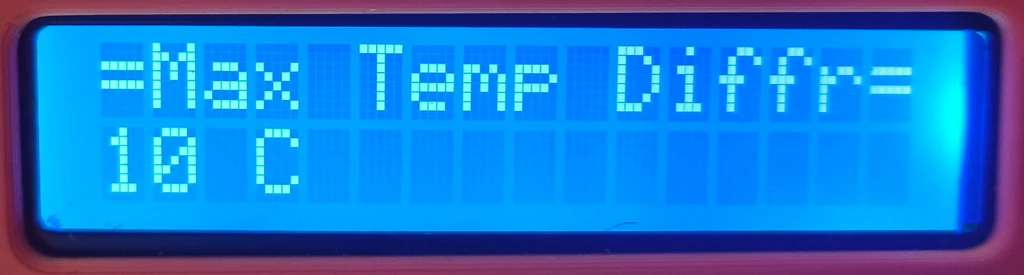
| Index name: | VAR_MAX_TEMP_DIFFERENCE |
| Index value: | 2 |
| Possible value: | 1 – max(INSIDE_SENSOR_MAX_TEMP – variables[VAR_MAX_TEMP_INSIDE] – 1, 1) |
| Description: | Maximum difference between inside and outside temperature. It only has effect when ventilation mode is AUTO. It defines the temperature range that will drive the ventilation fan and the doors. The fan will start at idle and doors at 30 degrees at the small temperature difference, but should reach max RPM and doors opened at 90 degrees at max difference. |
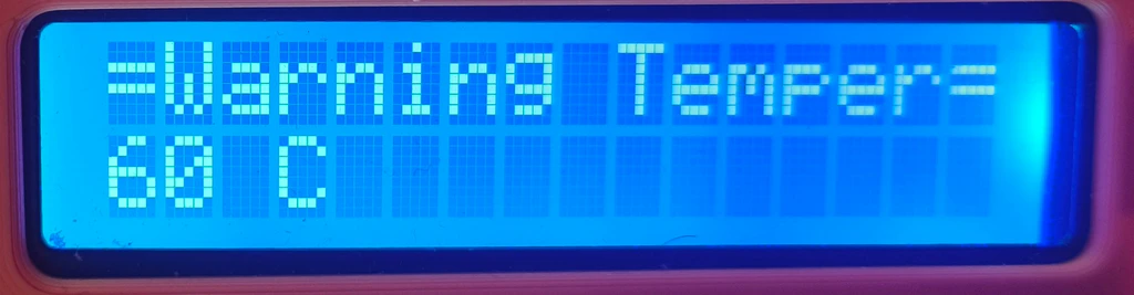
| Index name: | VAR_WARNING_TEMP |
| Index value: | 3 |
| Possible value: | (VAR_MAX_TEMP_INSIDE + 1) -min(variables[VAR_SHUTDOWN_TEMP] – 1, INSIDE_SENSOR_MAX_TEMP) |
| Description: | Temperature at which fire warning will be triggered. Both minimum and maximum varies based on other temperature settings. |
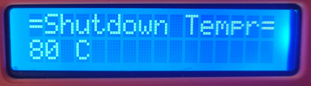
| Index name: | VAR_SHUTDOWN_TEMP |
| Index value: | 4 |
| Possible value: | (VAR_WARNING_TEMP + 1) – 80 |
| Description: | Temperature at which fire alert will be triggered, which should result in closing power relay to shutdown the printer (unless override is active). Minimum varies, 80 is chosen maximum. |
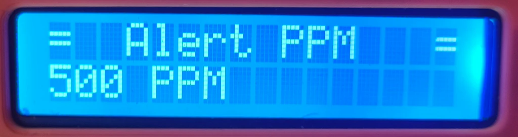
| Index name: | VAR_ALERT_PPM |
| Index value: | 5 |
| Possible value: | 30-255 |
| Description: | The PPM value of gas sensor reading when a fire warning will be triggered. The value is multiplied by 100. |
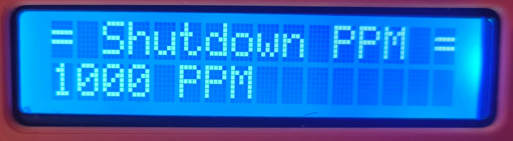
| Index name: | VAR_SHUTDOWN_PPM |
| Index value: | 6 |
| Possible value: | VAR_ALERT_PPM – 255 |
| Description: | The PPM value of gas sensor reading when a fire alert (printer shutdown treshold) will be triggered. The value is multiplied by 100. |
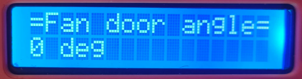
| Index name: | VAR_FAN_DOOR_ANGLE |
| Index value: | 7 |
| Possible value: | 0 = OFF 1 – 90 255 = FAN_DOOR_ANGLE_AUTO |
| Description: | Ventilation fan door angle. The value of 255 is for automatic control. |
| Index name: | VAR_FAN_DOOR_SPEED |
| Index value: | 8 |
| Possible value: | 0-255 |
| Description: | The speed at which the fan door angle should changed. The value is multiplied by 10 and means in how many milliseconds should the angle change by one degree. |
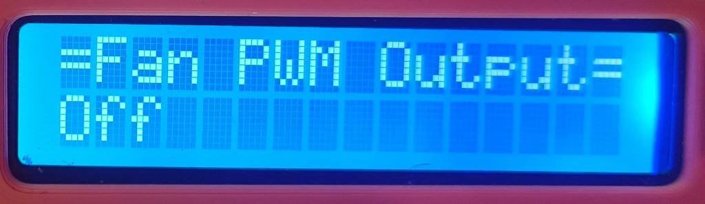
| Index name: | VAR_FAN_PWM |
| Index value: | 9 |
| Possible value: | 0 = OFF 20 – 100 |
| Description: | The PWM output to the ventilation fan. It is limited to min 20%, as below this value the voltage would be to low to spin the fan. |
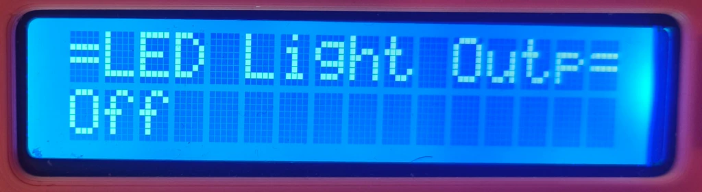
| Index name: | VAR_LED_ON |
| Index value: | 10 |
| Possible value: | 0 = LIGHT_LED_OFF 1 = LIGHT_LED_ON |
| Description: | Whether the LED stripe is ON or OFF. |
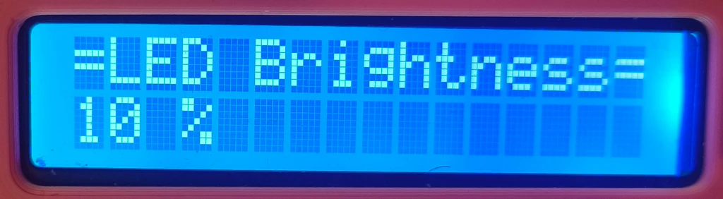
| Index name: | VAR_LED_PWM |
| Index value: | 11 |
| Possible value: | 0 – 100 |
| Description: | The PWM output applied to the LED stripe. From 0-100%. |
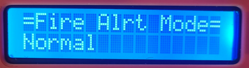
| Index name: | VAR_FIRE_ALERT_MODE |
| Index value: | 12 |
| Possible value: | 0 = FireAlertMode::NORMAL 1 = FireAlertMode::FIRE_WARNING 2 = FireAlertMode::FIRE_HAZARD |
| Description: | Fire alert mode. |
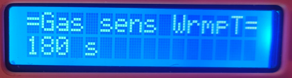
| Index name: | VAR_GASSENS_WARMUP_TIME |
| Index value: | 13 |
| Possible value: | 2 – 255 |
| Description: | Gas sensor warm up time. The value is multiplied by 10 and is in seconds. |
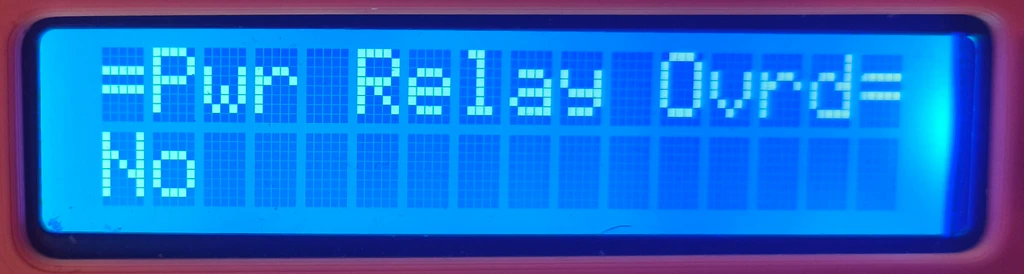
| Index name: | VAR_PWR_RELAY_OVERRIDE |
| Index value: | 14 |
| Possible value: | 0 = PWR_RELAY_OVERRIDE_OFF 1 = PWR_RELAY_OVERRIDE_ON |
| Description: | Whether the power relay override is on or off. When ON, the power relay will not be triggered OFF even in the case of fire alert. This option exists mainly for debugging purposes and early testing, when I wanted to prevent shutdown of the printer mid-printing due to some false silly bug or false sensor reading. It should be OFF most the times. |
| Index name: | VAR_ENABLE_WDT |
| Index value: | 15 |
| Possible value: | 0 = WDT_OFF 1 = WDT_ON |
| Description: | Whether the watchdog function is or on off. |
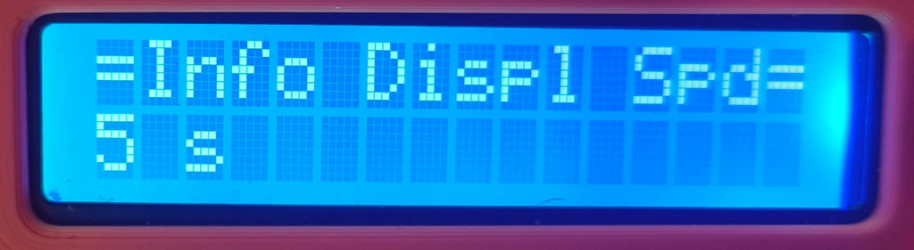
| Index name: | VAR_INFO_DISPLAY_SPEED |
| Index value: | 16 |
| Possible value: | 0 – 255 |
| Description: | The speed at which the Info Display rotates the information pages on the 16×2 LCD display. In seconds. |
| Index name: | VAR_LAST_FAN_DOOR_POSITION |
| Index value: | 17 |
| Possible value: | same as VAR_FAN_DOOR_ANGLE |
| Description: | Last position of fan door. This is being stored so the next time the Arduino UNO boots it restores the door to the last position (so they should not move actually). It is read-only, so cannot be changed using the control panel. |
From the table above I think you can deduce that these settings allow for a quite of variation in the printer enclosure operation. Going over all the details of the code is outside the scope of this article. The class mostly offers “getters” to public – to get values of the respective setting variable. The handling of displaying setting pages, handling the rotation encoder and pushbutton inputs, changing the values of variables , is done in private functions and methods:
// Helper methods
    void loadFromEEPROM();
    void saveToEEPROM();
    void enterVariableDisplayMode();
    void enterVariableSetupMode();
    void updateVariableValue();
    void exitToSetupOff();
    void displayCurrentVariable();
    void saveVariableToEEPROM(byte index, byte value);
    byte readVariableFromEEPROM(byte index);
    void checkButton();

    // Value range checks
    byte constrainValue(byte value, byte min, byte max);
    byte constrainAngleValue(byte value);

    void (*onVariableChangedCallback)(byte variable, byte newValue);  // Function pointer for the callback
like the above ones defined in the SettingsManager.h and implemented in the SettingsManager.cpp. For the stuff related to reading and saving variables from/to EEPROM, refer also to the EEPROM Library documentation.
And here are pictures of the real display:


Fire Watch
- Header file: FireWatch.h
- Cpp file: FireWatch.cpp
The FireWatch class is the guardian that continuously watches the inside and outside temperature, gas sensor reading and will trigger warnings/alerts when things go wild. For that, it uses the references to temperature sensors helper class, gas sensor helper class, Settings Manager class and others.
The system can be in one of three fire alert modes:
- FireAlertMode::NORMAL – This is the normal mode. No excessive temperatures and/or gas sensor reading happens. The power relay is ON so that the 3D printer has power.
- FireAlertMode::FIRE_WARNING – When switched to this mode, the inside temperature rose over the warning temperature (see VAR_WARNING_TEMP in SettingsManager) and/or the gas sensor reading rose over warning PPM level (see VAR_ALERT_PPM in SettingsManager). The Ventilation Control will also catch this situation and will command the ventilation fan for max RPM and fully open the ventilation door. The red LED will flash in 1 seconds interval and a warning tone will be played via the buzzer until the situation changes.The system so far just expects excessive temperature or fumes buildup inside the enclosure, not fire.
- FireAlertMode::FIRE_HAZARD – When falling to this mode, the inside temperature rose over the shutdown temperature (see VAR_SHUTDOWN_TEMP in SettingsManager) and/or the gas sensor reading rose over warning PPM level (see VAR_SHUTDOWN_PPM in SettingsManager). The Ventilation Control will catch this situation also and will command the ventilation fan to stop and the doors to closed position. As the system now considers this as fire condition, those actions should help slow down the extension of the fire. The power relay will be turned OFF, cutting the 3D printer off power (unless VAR_PWR_RELAY_OVERRIDE is set to ON). The red LED will flash in 200 milliseconds interval and a fire alert tone will be played via the buzzer.
The function that switches between those three fire alert modes is:
/**
	 * This function checks for fire hazard
	 */
	void doFireWatch();
and is being called from the main loop. This class is then in charge of the buzzer and the red LED located in the control panel. It also controls the power relay. The fire alert mode can also be changed using the control panel – to test the proper functionality of the system.
Take a look at these other functions inside the class, which also plays the important role in the logic of the fire watch class:
void triggerFireAlarm();
	void resetFireAlarm();
	void toneFireAlarmSiren();
	void toneWarningSiren();
	void switchPowerRelay(bool bOn, const char *lcdMessage, word waitTime);

	void handleAlert(FireAlertMode prevMode, FireAlertMode currMode);

	void updateStatusLED();
and these public ones:
/**
	 * Checks whether there was a stored file alarm and switched power relay ON/OFF
	 */
	void checkStoredFireAlarm();
	void switchPowerRelayOn();
	void switchPowerRelayOff();
	void setAlertMode(FireAlertMode currMode, bool bChangedFromSettings);
Ventilation Control
- Header file: VentilationControl.h
- Cpp file: VentilationControl.cpp
VentilationControl class is another major player in the whole printer enclosure control system “puzzle”. It controls the ventilation fan using PWM and also the fan doors. To be able to do that, it needs to know the inside temperature and gas sensor readings, so it holds reference to those sensors – via the FireWatch class. It is handy because these classes needs to cooperate in the event the fire warning / alert thresholds should be breached.
The main function, that is called from the main loop, is the controlVentilation() function:
/**
 * This function automatically controls ventilation fan speed and vent fan doors based on difference
 * of outside temeperature and inside temperature, and on how fast the converge
 *
 */
void VentilationControl::controlVentilation() {
      // Calculate the temperature difference and convergence rate
	float insideTemperature = fireWatch->getDHTSensors()->getInsideTemperature();
	//float outsideTemperature = fireWatch->getDHTSensors()->getOutsideTemperature();
    float tempDiff = NAN;
    float convergenceRate = NAN;
    SettingsManager* settingsManager = fireWatch->getSettingsManager();

    //if there is fire alarm, make sure doors are closed and fan is OFF, so there is as less air circulation as possible helping
    //starving the fire. Also, close doors and turn off fan if warning threshold is triggered and gas sensor has some PPM reading, that is possibly
    //fire developing
	if ((fireWatch->getAlertMode() == FireAlertMode::FIRE_HAZARD || settingsManager->getFireAlertMode() == FireAlertMode::FIRE_HAZARD) ||
			(fireWatch->getAlertMode() == FireAlertMode::FIRE_WARNING && fireWatch->getGasSensor()->getSensorValuePPM() > settingsManager->getAlertPPM())) {
		turnFanOff();
		//modify servo position only if differs from the one it is in
		/*if (fanDoorServo.read() != MIN_FAN_DOOR_ANGLE) {
			fanDoorServo.write(MIN_FAN_DOOR_ANGLE);
		}*/
		setFanDoorPosition(MIN_FAN_DOOR_ANGLE);
		return;
	}

	//compute temperature difference between inside and outside
    if (!isnan(insideTemperature) && !isnan(tempMaxInside)) {
    	//this will be negative until inside temperature is greater than threshold
    	tempDiff = insideTemperature - tempMaxInside;
    	convergenceRate = (tempDiff - prevTempDiff) / ((millis() - lastTempDiffUpdateTime) / 1000.0); // °C/s
    	lastTempDiffUpdateTime = millis();
    	prevTempDiff = tempDiff;
    }


    // Determine fan duty based on temperature difference and convergence rate, if control mode is set to AUTO
    byte fanDuty = FAN_OFF_DUTY;
    // Determine door position based on temperature difference and if not overridden by settings manager
    byte doorPosition = 0;

    //First check if enclosure is in fire warning mode. If so and there is no gas sensor reading, there is just high temperature inside, force fan to max. If there is
    //also gas sensor reading, fire is probably developing, then turn off the fan so it does not help the fire by moving the air and creating the column effect.
    //otherwise, the enclosure is in normal state, then decide whether by set for auto or manual control
    if (fireWatch->getAlertMode() == FireAlertMode::FIRE_WARNING) {
		if (fireWatch->getGasSensor()->getSensorValuePPM() < settingsManager->getAlertPPM()) {
			//in case of warning, but not critical PPM,  override the doors for max open
			fanDuty = FAN_MAX_DUTY;		//vent it out
			doorPosition = MAX_FAN_DOOR_ANGLE;		//vent it out
		} else {
			//if there is PPM detection, fire is probably developing, close the doors
			fanDuty = FAN_OFF_DUTY;
			doorPosition = MIN_FAN_DOOR_ANGLE;
		}
	} else {
		//Logic for determining fan duty when enclosure is in normal state
		if (settingsManager->getTempControlMode() == SettingsManager::AUTO_MODE) {
			if (!isnan(insideTemperature) && !isnan(tempMaxInside)) {
				fanDuty = calculateFanDuty(tempDiff, convergenceRate);

				/*#ifdef MK4SC_DEBUG
					// Debug output
					static unsigned long lastDebugTime = 0;

					if (DEBUG_TIME_ELAPSED(2000, lastDebugTime)) {

						char valueStr[10];
						dtostrf(insideTemperature, 0, 2, valueStr);

						DEBUG_PRINT_F(F("Insd temp: %s °C"), valueStr);

						dtostrf(outsideTemperature, 0, 2, valueStr);

						DEBUG_PRINT_F(F(", Outsd temp: %s °C"), valueStr);

						dtostrf(tempDiff, 0, 2, valueStr);

						DEBUG_PRINT_F(F(", Temp diff: %S °C"), valueStr);

						dtostrf(convergenceRate, 0, 2, valueStr);

						DEBUG_PRINT_F(F(", Convergence Rate: %s °C/s"), convergenceRate);
						DEBUG_PRINTLN_F(F(", Fan Duty: %d \%"), fanDuty);

						DEBUG_RESET_TIME(lastDebugTime);
					}

				#endif*/
			} else {
				//mode is auto, but temperature readings are invalid, thus, cannot control fan based on temperatures
				fanDuty = FAN_OFF_DUTY;
			}
		} else {
			//will return direct fan PWM duty from  FAN_IDLE_DUTY - FAN_MAX_DUTY
			fanDuty = settingsManager->getFanPWM();
		}


		//Logic to get fan door angle when enclosure is in normal state
		if (settingsManager->getFanDoorAngle() == SettingsManager::FAN_DOOR_ANGLE_AUTO) {
			if (!isnan(tempDiff)) {
				doorPosition = calculateDoorPosition(tempDiff);
			} else {
				//no temp diff means inside, outside or both temperatures are invalid
				doorPosition = MIN_FAN_DOOR_ANGLE;
			}
		} else {
			doorPosition = settingsManager->getFanDoorAngle();
		}
	}

    // Fan control logic
    if (fanDuty >= FAN_IDLE_DUTY) {
        if (!fanOn) {
            turnFanOn(); // Turn on the fan relay
        }
        //if fan is on, we have PWM controller and at least 1 second passed since switching relay ON, start setting up PWM
        if (fanOn && pwmController && ((millis() - fanRelayPowerOnTime) > 1000)) {

          if (lastFanDuty != fanDuty) {
        	  pwmController->setPwmDuty(fanDuty, fanPWMPIN);
        	  lastFanDuty = fanDuty;
          }

          /*#ifdef MK4SC_DEBUG
				// Debug output
				static unsigned long lastDebugTime = 0;

				if (DEBUG_TIME_ELAPSED(2000, lastDebugTime)) {

					DEBUG_PRINTLN_F(F("Fan Duty: %d \%"), fanDuty);

					DEBUG_RESET_TIME(lastDebugTime);
				}

			#endif*/
        }
    } else {
        turnFanOff(); // Turn off the fan relay
    }

    //update fan door speed in case it changed
    word currDoorSpeed = settingsManager->getFanDoorSpeed();
    if (currDoorSpeed != fanDoorSpeed) {
    	fanDoorSpeed = currDoorSpeed;
    }

    //set new door position. This will change over time, not instantly
    setFanDoorPosition(doorPosition);
}
Even though it might seem long in the above “code print-out”, there are a lot of comments 🙂 The function needs to determine what the fan PWM output and fan door angle should be and set those values. For that, it needs to check several things. Is there a fire warning or actual alarm? The FireWatch class will just trigger alarms and kill printer from power if required. This class will cooperate in that it will stop the fan and close fan doors (in case of fire alarm). In the case of fire warning, it will apply full fan power and fully open fan doors. Yes, if there is a fire, it will temporarily accelerate it, but in case of fire warning we hope just for excessive temperature and/or fumes buildup and want to help reduce it.
If condition are normal, the function checks if automatic ventilation control is turned on. And it will calculate the fan PWM output and fan door position from the difference of inside and maximum inside temperature. The bigger the difference (over maximum inside temperature) , the more power to the ventilation fan and bigger fan door angle should be applied. The two functions that do respective calculations are:
byte calculateFanDuty(float tempDiff, float convergenceRate);
byte calculateDoorPosition(float tempDiff);
If automatic mode is disabled, it will just apply the ventilation fan power and fan door angle as set by the control panel (which is both off by default).
The “final set-up of the values” happens at the end of the function at the following lines:
// Fan control logic
    if (fanDuty >= FAN_IDLE_DUTY) {
        if (!fanOn) {
            turnFanOn(); // Turn on the fan relay
        }
        //if fan is on, we have PWM controller and at least 1 second passed since switching relay ON, start setting up PWM
        if (fanOn && pwmController && ((millis() - fanRelayPowerOnTime) > 1000)) {

          if (lastFanDuty != fanDuty) {
        	  pwmController->setPwmDuty(fanDuty, fanPWMPIN);
        	  lastFanDuty = fanDuty;
          }

          /*#ifdef MK4SC_DEBUG
				// Debug output
				static unsigned long lastDebugTime = 0;

				if (DEBUG_TIME_ELAPSED(2000, lastDebugTime)) {

					DEBUG_PRINTLN_F(F("Fan Duty: %d \%"), fanDuty);

					DEBUG_RESET_TIME(lastDebugTime);
				}

			#endif*/
        }
    } else {
        turnFanOff(); // Turn off the fan relay
    }

    //update fan door speed in case it changed
    word currDoorSpeed = settingsManager->getFanDoorSpeed();
    if (currDoorSpeed != fanDoorSpeed) {
    	fanDoorSpeed = currDoorSpeed;
    }

    //set new door position. This will change over time, not instantly
    setFanDoorPosition(doorPosition);
Note the first part. The ventilation fan power is switched on/off by a relay. So the code also waits for the time of one second before applying first PWM output to the fan after the relay has been switched on.
Neither of setting the fan PWM or the fan door angle are “simple” writes to the respective Arduino output to which the fan PWM signal and fan door servo control signal are connected. The fan control is implemented based on this article – which required “hacks” – modifications of Arduino registries/ timers, that are used to control PWM outputs on Arduino UNO. Due to these changes, “classic servo” library also couldn’t be used. But the “why’s” are more described in this section, so refer to that.
Info Display
- Header file: InfoDisplay.h
- Cpp file: InfoDisplay.cpp
The display of various information on the 16×2 display is implemented in the InfoDisplay class. It displays ten different information pages, which are summarized below:
| ID: | INFO_PAGE_IATH |
| ID Value: | 0 |
| Example: | -Insid temp/hum- T=23.3,H=53 |
| Description: | Inside temperature and humidity. |
| ID: | INFO_PAGE_OATH |
| ID Value: | 1 |
| Example: | -Outsd temp/hum- T=18.9,H=53 |
| Description: | Outside temperature and humidity. |
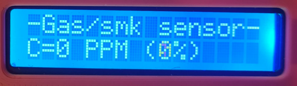
| ID: | INFO_PAGE_GASSENS |
| ID Value: | 2 |
| Example: | -Gas/smk sensor- C=0 PPM (0%) |
| Description: | The reading of gas smoke sensor, in PPM and percent. Or gas sensor warm up time if sensor is not yet calibrated. |
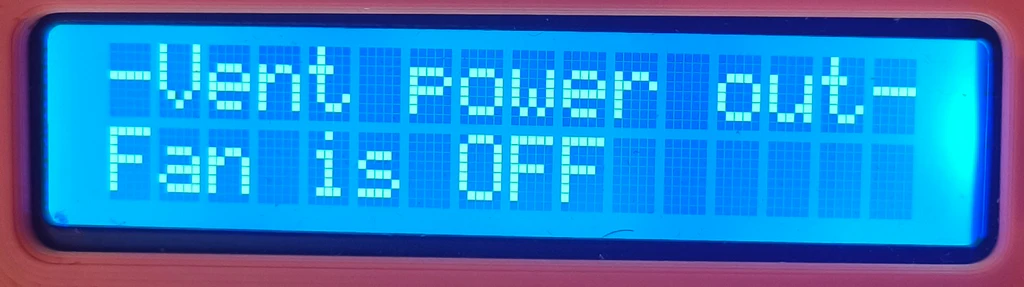
| ID: | INFO_PAGE_VENT1 |
| ID Value: | 3 |
| Example: | -Vent power out- Fan is OFF |
| Description: | Displays ventilation fan control mode – AUTO, ON, OFF and ventilation fan RPM. |
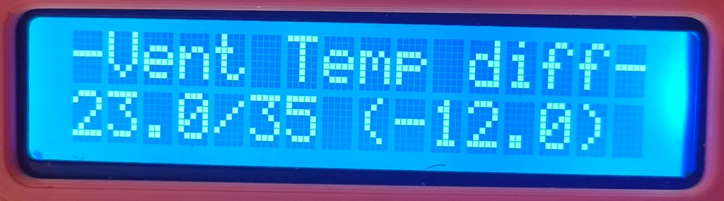
| ID: | INFO_PAGE_VENT2 |
| ID Value: | 4 |
| Example: | -Vent Temp diff- 23.0/35 (-12.0) |
| Description: | Displays inside temperature, max inside temperature and their difference. If ventilation control is in AUTO mode, the ventilation should start/stop once the temperatures meet. |
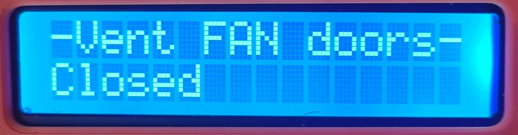
| ID: | INFO_PAGE_VENT3 |
| ID Value: | 5 |
| Example: | -Vent FAN doors- Closed |
| Description: | Displays ventilation doors angle and whether they work by automatic or manual control. |
| ID: | INFO_PAGE_LIGHT |
| ID Value: | 6 |
| Example: | -LED strip ligh- Off |
| Description: | Displays whether the LED stripe is turned ON or OFF and the brightness – % of max power applied to it. |
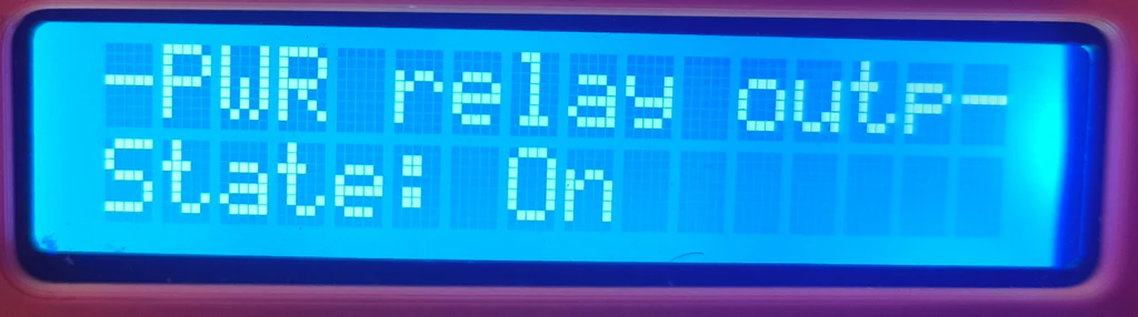
| ID: | INFO_PAGE_POWER_RELAY |
| ID Value: | 7 |
| Example: | -PWR relay outp- State: On |
| Description: | Displays whether the power relay is engaged or not and if it is overridden (forced to) or not. |
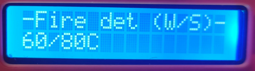
| ID: | INFO_PAGE_FIRE |
| ID Value: | 8 |
| Example: | -Fire det (W/S)- 60/80C |
| Description: | Displays the fire warning / shutdown temperature. |
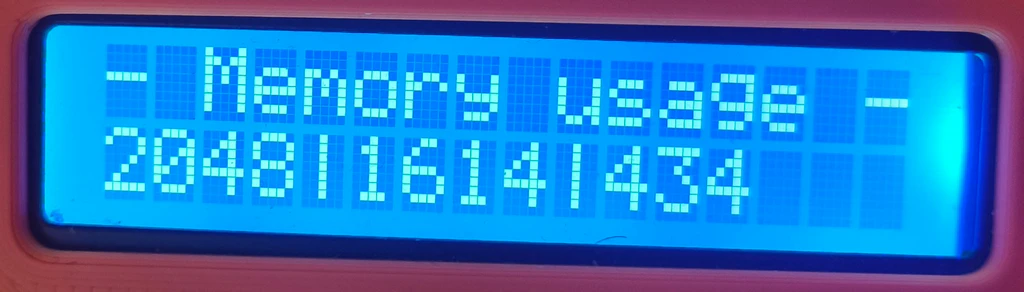
| ID: | INFO_PAGE_MEM |
| ID Value: | 9 |
| Example: | -Memory usage – 2048|1614|434 |
| Description: | Displays Arduino memory usage – Total memory/Used memory/Free memory. |
The first row of the display always displays the “title” of the current page being shown. It is mostly abbreviated , because 16 characters is not much to write essays with. The class automatically switches pages after the pass of defined time and if allowed by the settings. The pages can also be switched by the rotation of the rotary encoder.
There are two main functions. The:
void init();which is called from the setup() function during Arduino initialization. And the:
void displayInfoPage();which is called from the main loop. This one does the display of various information pages on the 16×2 display.
I believe there is nothing extra complicated hidden in the code of InfoDisplay.cpp file, which contains the implementation of this class, so I will not go into details here and will leave it for you to study.
And to have some pictures:


The “common.h” file
The common.h file, and common.cpp file contains constant definitions, and macros, that are used by many classes and code throughout this project. For example:
constexpr byte FAN_IDLE_DUTY = 20;   // Minimum duty cycle for idle fan speed
constexpr byte FAN_OFF_DUTY = 0;    // Duty cycle for the fan to stop spinning
constexpr byte FAN_MAX_DUTY = 100;  // Maximum duty cycle for the fan
which are pretty self explanatory constants, I think 🙂
But there are also “string” constants, defined liked this in the .h file:
extern const char SM_STR_FAM_NORMAL[] PROGMEM;
extern const char SM_STR_FAM_WARNING[] PROGMEM;
extern const char SM_STR_FAM_HAZARD[] PROGMEM;
which are just sort of “pre-definitions”, the real value is assigned in the .cpp file:
const char SM_STR_FAM_NORMAL[] PROGMEM = "Normal";
const char SM_STR_FAM_WARNING[] PROGMEM = "Fire Warning";
const char SM_STR_FAM_HAZARD[] PROGMEM = "Fire Hazard";
The interesting here is the use of PROGMEM . You can meet constants defined like that also in another files, not just here. Maybe you have never encountered this keyword, as I did not – before this project. Normally, all constant values are store in the stack. But we can deplete the avaiable memory in Arduino UNO pretty fast storing there a higher amount of “string” variables. The PROGMEM keyword says to the compiler to store the value in the program memory instead. But this also changes the way we can work with that string. We cannot just pass it to function like with normal “const char*” string, but rather we have to load it from the program memory to the stack. See the example below:
lcdHelper->printTextToLCD(_loadFlashString(reinterpret_cast<const __FlashStringHelper*>(SM_STR_FAM_NORMAL)), 1);The above code is from SettingsManager.cpp. It displays the shown SM_STR_FAM_NORMAL string on the first line of the 16×2 LCD display using LCD1602Helper class. The first argument expects classic “const char*“, just like many classic string functions. But we have to use the _loadFlashString function to retrieve the string stored in program memory and convert it to “const char*“. The _loadFlashString is also defined in our common.h/common.cpp:
char* _loadFlashString(const __FlashStringHelper* flashStr) {
    static char buffer[LCD_STRING_MAX_LEN + 1] = {0};  // +1 for null terminator
    memset(buffer, 0, sizeof(buffer));  // Clear the buffer before copying, this is because left-over chars from previous calls, that would otherwise be there
    strncpy_P(buffer, (PGM_P)flashStr, LCD_STRING_MAX_LEN);
    buffer[LCD_STRING_MAX_LEN] = '\0';  // Ensure null termination
    return buffer;
}
The function creates char buffer, copies the string from program memory to it, and returns the buffer (pointer to the first character). Each call of this function creates a new buffer. There is a similar function like this, that is reserved to load debug messages and is different in that it re-uses one permanent buffer:
// Define global buffers (so only one copy exists in the whole program)
char debugBuffer[DEBUG_BUFFER_SIZE];
char debugFlashStrBuffer[DEBUG_BUFFER_SIZE];

void _loadDebugFlashString(const __FlashStringHelper* flashStr, char* buffer, size_t bufferSize) {
    memset(buffer, 0, bufferSize);  // Clear the buffer
    strncpy_P(buffer, (PGM_P)flashStr, bufferSize - 1);
    buffer[bufferSize - 1] = '\0';  // Ensure null termination
}
This function is then used in the debug macros:
#define MK4SC_DEBUG  // Comment this line to disable debugging

#ifdef MK4SC_DEBUG
    #define DEBUG_PRINTER Serial /**< Define where debug output will be printed.**/

	#define DEBUG_BUFFER_SIZE 128  /**< Buffer size for the debug messages. */
    extern char debugBuffer[DEBUG_BUFFER_SIZE];  // Global buffer for all debug macros
    extern char debugFlashStrBuffer[DEBUG_BUFFER_SIZE];  //global buffer for loading debug message stored in PROGMEM

    void _loadDebugFlashString(const __FlashStringHelper* flashStr, char* buffer, size_t bufferSize);

    #define DEBUG_INIT(baud) DEBUG_PRINTER.begin(baud); while (!DEBUG_PRINTER)

    #define DEBUG_PRINT(fmt, ...) { \
        memset(debugBuffer, 0, sizeof(debugBuffer)); \
        int len = snprintf(debugBuffer, sizeof(debugBuffer), fmt, ##__VA_ARGS__); \
        debugBuffer[sizeof(debugBuffer) - 1] = '\0'; \
        if (len > 0 && len < sizeof(debugBuffer)) DEBUG_PRINTER.print(debugBuffer); \
    }

    #define DEBUG_PRINTLN(fmt, ...) { \
        memset(debugBuffer, 0, sizeof(debugBuffer)); \
        int len = snprintf(debugBuffer, sizeof(debugBuffer), fmt, ##__VA_ARGS__); \
        debugBuffer[sizeof(debugBuffer) - 1] = '\0'; \
        if (len > 0 && len < sizeof(debugBuffer)) DEBUG_PRINTER.println(debugBuffer); \
    }

    #define DEBUG_PRINT_F(fmt, ...) { \
        _loadDebugFlashString(fmt, debugFlashStrBuffer, DEBUG_BUFFER_SIZE); \
        DEBUG_PRINT(debugFlashStrBuffer, ##__VA_ARGS__); \
    }

    #define DEBUG_PRINTLN_F(fmt, ...) { \
        _loadDebugFlashString(fmt, debugFlashStrBuffer, DEBUG_BUFFER_SIZE); \
        DEBUG_PRINTLN(debugFlashStrBuffer, ##__VA_ARGS__); \
    }

    // Macro to check if the specified interval has passed
	#define DEBUG_TIME_ELAPSED(interval, lastTimeVar) (millis() - (lastTimeVar) >= (interval))

	// Macro to reset the interval time
	#define DEBUG_RESET_TIME(lastTimeVar) (lastTimeVar = millis())

#else
    #define DEBUG_INIT(baud)
    #define DEBUG_PRINT(fmt, ...)
    #define DEBUG_PRINTLN(fmt, ...)
    #define DEBUG_PRINT_F(fmt, ...)
    #define DEBUG_PRINTLN_F(fmt, ...)
	#define DEBUG_TIME_ELAPSED(interval, lastTimeVar) (false)
    #define DEBUG_RESET_TIME(lastTimeVar)
#endif
respectively, by those that end with _F, which signals that they expect the debug message that is located in program memory.
The “other” classes
There are several “other” or “helper” classes used in this project that we should briefly touch on too:
LCD1602Helper
- Header file: LCD1602Helper.h
- Cpp file: LCD1602Helper.cpp
The LCD1602Helper, is, as name suggests, a helper class. It is used throughout the project to print text and various values on the 16×2 LCD display. Below it the definition:
#ifndef LCD1602HELPER_H
#define LCD1602HELPER_H

#include <Arduino.h>
#include <LiquidCrystal_I2C.h>
#include "LCDHelper.h"
#include "common.h"

constexpr byte LCD1602_WIDTH = 16;
constexpr byte LCD1602_ROWS = 2;

class LCD1602Helper : public LCDHelper {
private:
    LiquidCrystal_I2C* lcd; // I2C 1602 LCD display

    //last rows
    char lastRow1[LCD1602_WIDTH + 1] = {0};
    char lastRow2[LCD1602_WIDTH + 1] = {0};

    void printRows(byte row, const char* row1, const char* row2);
    void printRow(const char* text, byte row);

public:
    // Constructor
    LCD1602Helper(LiquidCrystal_I2C* lcd);

    // Overriding base class methods
    void printTextToLCD(const char* text, byte row) override;
    void printFormattedTextToLCD(byte row, const char* fmt, ...) override;
    void displayFloatValue(const char* title, float value, const char* unit) override;
    void displayFloatValue(const char* title, float value, const char* unit, byte precision, byte row) override;
    void display2FloatValues(const char* title1, float value1, const char* unit1, byte precision1,
                             const char* title2, float value2, const char* unit2, byte precision2, byte row) override;
    void displayByteValue(const char* title, byte value, const char* unit) override;
    void displayByteValue(const char* title, byte value, const char* unit, byte row) override;
    virtual void displayWordValue(const char *title, word value, const char *unit) override;
    virtual void displayWordValue(const char *title, word value, const char *unit, byte row) override;
    void clear() override;
    void clearRow(byte row);

    static void sanitizeLCDRow(char* row, size_t length);

    LiquidCrystal_I2C* getLCD();
};

#endif
The 16×2 display is and LCD display with 2 rows, each can display 16 characters. We use mainly byte, word and float variables in the project, so I am sure you can easily decipher which helper methods are used for which ones.
GenericPWM and UnoPWM
- Header file: GenericPWM .h, UnoPWM.h
- Cpp file: GenericPWM .cpp, UnoPWM.cpp
The GenericPWM and UnoPWM are classes encapsulating the functionality of custom PWM control. Here focused on controlling PC-based ventilation fan (writing about it in the Arduino PIN assignments chapter and in Ventilation Control chapter).
The GenericPWM class is actually an “interface” or super-class:
#ifndef GENERIC_PWM_H
#define GENERIC_PWM_H

#include <Arduino.h>

class GenericPWM {
public:
    virtual ~GenericPWM() {}

    virtual void setupTimer() = 0;
    virtual void setPwmDuty(byte duty, byte pwmPin) = 0;
};

#endif
for UnoPWM (and possible others):
#ifndef UNO_PWM_H
#define UNO_PWM_H

#include "GenericPWM.h"

/**
 * @class UnoPWM
 * @brief Class for configuring and controlling PWM on an Arduino Uno.
 *
 * This class allows generating PWM signals on pins 3, 9, 10, and 11 with configurable frequencies.
 * It provides fine control over Timer1 (for pins 9 and 10) and Timer2 (for pins 3 and 11), allowing
 * phase-correct PWM operation with adjustable duty cycles.
 *
 * Features:
 * - Supports configuring Timer1 and Timer2 for PWM output.
 * - Allows enabling/disabling individual PWM pins via flags.
 * - Computes appropriate timer top values based on the desired frequency.
 * - Provides functions to set PWM duty cycle dynamically.
 */
class UnoPWM : public GenericPWM {
private:
    word pwmFreqHz; ///< Desired PWM frequency in Hz
    word tcnt1Top;  ///< Computed TOP value for Timer1
    byte tcnt2Top;  ///< Computed TOP value for Timer2

    byte pwmPin1; ///< Pin assigned to Timer1 Channel A (default: 9)
    byte pwmPin2; ///< Pin assigned to Timer1 Channel B (default: 10)
    byte pwmPin3; ///< Pin assigned to Timer2 Channel B (default: 3)
    byte pwmPin4; ///< Pin assigned to Timer2 Channel A (default: 11)

    byte flags; ///< Configuration flags to enable specific timers and PWM pins

    /**
     * @brief Calculates the TOP value for Timer1 and Timer2 based on the desired frequency.
     */
    void calculateTop();

    /**
     * @brief Configures Timer1 for phase-correct PWM operation.
     */
    void setupTimer1();

    /**
     * @brief Configures Timer2 for fast PWM operation.
     */
    void setupTimer2();

public:
    // Default PWM pin assignments
    static constexpr byte PWM_PIN1 = 9;
    static constexpr byte PWM_PIN2 = 10;
    static constexpr byte PWM_PIN3 = 3;
    static constexpr byte PWM_PIN4 = 11;

    // Flags for configuring timers
    static constexpr byte FLAG_CONFIG_TIMER1 = 1;  ///< Enable Timer1 (pins 9, 10)
    static constexpr byte FLAG_CONFIG_TIMER2 = 2;  ///< Enable Timer2 (pins 3, 11)

    // Flags for enabling individual PWM pins
    static constexpr byte FLAG_ENABLE_PIN1 = 4;  ///< Enable PWM on pin 9
    static constexpr byte FLAG_ENABLE_PIN2 = 8;  ///< Enable PWM on pin 10
    static constexpr byte FLAG_ENABLE_PIN3 = 16; ///< Enable PWM on pin 3
    static constexpr byte FLAG_ENABLE_PIN4 = 32; ///< Enable PWM on pin 11

    /**
     * @brief Constructor to initialize the UnoPWM object.
     *
     * @param pwmFreqHz Desired PWM frequency.
     * @param pwmPin1 PWM pin associated with Timer1 Channel A (default: 9).
     * @param pwmPin2 PWM pin associated with Timer1 Channel B (default: 10).
     * @param pwmPin3 PWM pin associated with Timer2 Channel B (default: 3).
     * @param pwmPin4 PWM pin associated with Timer2 Channel A (default: 11).
     * @param flags Configuration flags for enabling timers and PWM pins.
     */
    UnoPWM(word pwmFreqHz, byte pwmPin1 = PWM_PIN1, byte pwmPin2 = PWM_PIN2, byte pwmPin3 = PWM_PIN3, byte pwmPin4 = PWM_PIN4, byte flags = (FLAG_CONFIG_TIMER1 | FLAG_ENABLE_PIN1));

    /**
     * @brief Sets up the timers based on the provided flags.
     */
    void setupTimer() override;

    /**
     * @brief Sets the PWM duty cycle for a given pin.
     *
     * @param duty Duty cycle percentage (0-100).
     * @param pwmPin The pin on which to set the duty cycle.
     */
    void setPwmDuty(byte duty, byte pwmPin) override;

    /**
     * @brief Retrieves the computed TOP value for Timer1.
     *
     * @return Timer1 TOP value.
     */
    word getTcnt1Top() const { return tcnt1Top; }

    /**
     * @brief Retrieves the computed TOP value for Timer2.
     *
     * @return Timer2 TOP value.
     */
    byte getTcnt2Top() const { return tcnt2Top; }
};


#endif
The UnoPWM is an implementation of Timer1 modifications for Arduino UNO required for controlling PC fan via 25KHz PWM signal, as described in the How to properly control PWM fans with Arduino article. The class is written in more generic way, so should allow also for another PWM frequencies, not just 25KHz. But it is used with 25KHz in this project.
DHTAsyncSensors
- Header file: DHTAsyncSensors.h
- Cpp file: DHTAsyncSensors.cpp
The DHTAsyncSensors is a helper class that encapsulated two instances of DHTAsync sensor variables, which represents our inside and outside temperature/humidity sensors. The sensors are read in asynchronous way (opposed to standard DHT library) and if you missed it above, here is why. The class declaration looks as follows:
#ifndef DHT_SENSORS_H
#define DHT_SENSORS_H

#include <DHT_Async.h>
#include "common.h"

constexpr word DEFAULT_MEASUREMENT_INTERVAL = 2000;
constexpr word READ_FAIL_TRESHOLD = 6000;

class DHTAsyncSensors {
private:
	DHT_Async insideSensor;
	DHT_Async outsideSensor;

    byte insideSensorPin;
    byte outsideSensorPin;
    byte insideSensorType;
    byte outsideSensorType;

    float insideTemperature;
    float insideHumidity;
    float outsideTemperature;
    float outsideHumidity;

    word insideMeasurementInterval;
    word outsideMeasurementInterval;
    unsigned long lastInsideMeasurementTime;
    unsigned long lastOutsideMeasurementTime;

public:

    DHTAsyncSensors(byte insideSensorPin, byte insideSensorType, byte outsideSensorPin, byte outsideSensorType , word measurementInterval, word outsideMeasurementInterval);

    bool measureInsideEnvironment();
    bool measureOutsideEnvironment();
    bool measureEnvironments();

    float getInsideTemperature() const { return insideTemperature; }
    float getInsideHumidity() const { return insideHumidity; }
    float getOutsideTemperature() const { return outsideTemperature; }
    float getOutsideHumidity() const { return outsideHumidity; }

    bool isInsideValid() const { return !(isnan(insideTemperature) && isnan(insideHumidity)); }
    bool isOutsideValid() const { return !(isnan(outsideTemperature) && isnan(outsideHumidity)); }
    bool areValuesValid() const { return isInsideValid() && isOutsideValid(); }
};

#endif
There isn’t anything complex hidden in the implementation – so, again, study it yourself 🙂
MQ2GasSensorNonBlocking
- Header file: MQ2GasSensorNonBlocking.h
- Cpp file: MQ2GasSensorNonBlocking.cpp
The MQ2GasSensorNonBlocking is a class that wraps the work with MQ2 gas sensor. It reads the gas sensor value using it’s analog signal (but also allows to set callback function for the digital input). It does not simply read the analog value (well, at the end of code… it does), but it does so using more complex approach described in more details in the: Smoke Detector using MQ2 Gas Sensor and Arduino article, which involves multiple readings, average values, gas curves and other magic.
Before meaningful measurements can be taken, the sensor must be calibrated to determine its baseline resistance (R₀) in clean air. This calibration logic is handled internally by the class and is triggered from the main loop:
//calibrate gas sensor
	byte gasSensState = gasSensor.calibrateGasSensor();
	//if calibrating right now, skip everything else
	if (gasSensState == MQ2GasSensorNonBlocking::SENSOR_STATE_CALIBRATING) {
		return;
	}
It triggers the calibration after defined time (180 seconds by default) for which the sensor should be powered to ” warm-up” and after which its readings are trusted. During the calibration the class repeatedly samples the analog pin, filters noise by averaging multiple readings, and calculates the sensor resistance (Rₛ). From the ratio Rₛ/R₀, the code can estimate gas concentration in PPM using predefined gas curves. This logic is encapsulated in functions responsible for calibration, resistance calculation, and PPM conversion, keeping the main application code clean and readable.
The class is designed to be non-blocking, meaning it avoids long delays that would otherwise stall the main loop. Periodic sampling is handled using timing checks based on millis(), allowing the gas sensor to coexist with other time-critical components such as PWM fan control, servo control, interrupts, and user input. In addition to analog PPM readings, the class also supports the MQ-2’s digital output by attaching an interrupt or callback via the digital pin, enabling immediate reaction to threshold-based gas detection while still maintaining continuous analog monitoring.
To mention some code, this private function:
/**
   * Function does the initial sensor calibration. It performs initial resistance reading.
   *
   * @return When calibration is finished, it will return true. Otherwise, it returns false.
   */
  bool calibrateSensor();
does the actual calibration, even though triggered by the public:
/**
     * This function performs initial sensor calibration. It waits for sensor warm-up and does initial resistance reading. It is non-blocking.
     * You can tell when sensor is calibrated by calling {@link #isSensorCalibrated()}.
     */
    byte calibrateGasSensor();
and those two you will use to read sensor value:
/**
     * This functions returns the raw sensor analog value.
     */
    word getSensorValue() const;
    /**
     * This functions returns sensor value recalculated to PPM.
     */
    word getSensorValuePPM() const;
WiderServoTimer2
- Header file: WiderServoTimer2.h
- Cpp file: WiderServoTimer2.cpp
The last class I want to mention is our own, slightly modified, version of ServoTimer2 library. Again, if you missed it, read here why we need this library to control the fan door servo and why we are not using the standard Servo library.
The only changes that I made in our WiderServoTimer2 library against the original ServoTimer2, are changes in the minimum and maximum pulses:
#define MIN_PULSE_WIDTH       600        // the shortest pulse sent to a servo

#define MAX_PULSE_WIDTH      2400        // the longest pulse sent to a servo
Why … you might ask? In the original ServoTimer2 library, the effective servo pulse width range is more conservative than the standard Arduino Servo library and is typically limited to approximately 750 µs (minimum) and 2250 µs (maximum). While this narrower range is safe for many servos, it proved insufficient in this project, as it did not allow the servo to reach the full required mechanical travel, particularly near the closed and fully open fan door positions.
By expanding the usable pulse range, the servo is now able to achieve (almost) the full 0°–90° operating range required by the fan door mechanism. This ensures that the doors can fully close (so the temperature does not escape from the enclosure) and fully open (maximum airflow during ventilation). The widened limits better match the real capabilities of the specific servo used, while still remaining within safe and commonly supported pulse widths for standard hobby servos. This modification was necessary to achieve correct mechanical end positions, not increased speed or force, and it improves overall system reliability and control accuracy.
DHTSensors and MQ2GasSensor
- Header file: DHTSensors .h, MQ2GasSensor.h
- Cpp file: DHTSensors .cpp, MQ2GasSensor.cpp
You may notice the source files for DHTSensors and MQ2GasSensor classes within the downloaded archive. These are first versions of the control classes, that I used before I found out that the way they are reading the sensors (blocking way), is the main reason the control panel feedback and control was so slugish. The code simply didn’t run often enough, because the read fromsensors was causing too long delays. Than the classes were replaced with their non-blocking versions – DHTAsyncSensors and MQ2GasSensorNonBlocking . I kept the classes in the source, just in case you would like to study the differences. The files are not used in the compilation.
Downloads
And here, finally, the reason why you are reading all of that till down here, the download of the source code 🙂
and other files:
Bugs…
There are some bugs running around that I did not resolve yet. I know about these:
- I did not really test / debug the watch dog timer function.
- Sometimes, the Arduino UNO just freezes.
- The ventilation fan RPM reading is sort of unreliable.
- The outside DHT11 will not provide valid data until the push button on the rotary encoder is not pushed at least once. None of the medicine, hacks or workarounds that I tries worked. I will probably just replace it with DHT22 as is used for inside sensor, as it works without issues.
Links
Links related to Arduino programming:
- Arduino Documentation
- EEPROM Library
- Servo Library (even thought not used in this project)
- ServoTimer2 Library
- DHT-Async Library
Links related to ventilation system:
- PWN Fan controller with temp sensing and button override
- How to properly control PWM fans with Arduino
- Secrets of Arduino PWM
- Timer Interrupts and PWM Pins
Links related to fire protection system:
- Smoke Detector using MQ2 Gas Sensor and Arduino
- How MQ2 Gas/Smoke Sensor Works? & Interface it with Arduino
- How Does MQ-2 Flammable Gas and Smoke Sensor Work with Arduino?
Other usefull links:
All episodes of the series:
- The Tale of Building an enclosure for Prusa MK4S – The Idea
- The Tale of Building an enclosure for Prusa MK4S – Printed parts
- The Tale of Building an enclosure for Prusa MK4S – Wiring
- The Tale of Building an enclosure for Prusa MK4S – Programming – this one 🙂