
In this chapter you can read about the 3D prints that I’ve printed when working on my printer enclosure. Some were modified, some I’ve modeled myself.
Although, don’t expect to find here exact assembly instructions. That would require much more writing and reading. And there is a lot to read already, because, if you want to get into it, just like in another chapters, you will have to also study the referenced used projects a little bit.
Anyway, if you take the road, maybe you will not like my design and would like to create your own, or use different modifications… so I think it dose not matter that much if I skip the couple of screws I used here and there.
The “base” box
For the main part (the top part of the enclosure, all the parts around the lid) I followed the official Original Prusa Tutorial for Ikea Lack Enclosure: Prusa Printer Enclosure V2 – with MMU2S support and used the unmodified 3D print files from Prusa Enclosure V2 – MMU2S.

I printed from PETG and and right then I’ve experienced first issues for which I decided to build the enclosure for – warping. The parts for the enclosure are pretty big, long and it happened to me that most of them slightly lifted from the print bed and warped. So they are not perfectly straight as they should be. I just wasn’t able to print those big parts perfectly on my opened printer. Kind of funny problem, if you think about it 🙂 Anyway, I didn’t want to waste material and time and it wasn’t that bad to prevent me from assembling the parts together, so I kept them as they were.
But even a big cardbox and quality fixative can help with that – when you need to print parts for printer enclosure that should be printed on enclosed printer.
The bottom parts at the “table legs”
Maybe, in the first introductory article you noticed that my printer enclosure just stands on the table. I did not use the tutorial solution with two Ikea Lack tables, where one serves it’s actual purpose – a table – a stand at which the enclosure is mounted. Reading this back, Ok, actually, I did, but with different table. But the thing is, that the enclosure is not fixed to the table (which I didn’t want to do). So I was looking for solution that would let me easily remove the enclosure from the table, but still have it kind of “fixed”. The surface of the table is a bit slippery. You can just use the bottom parts from the files for Prusa Enclosure V2 – MMU2S ,it will work too, but I printed parts from Better removable Prusa Enclosure V2.

I printed the rear.stl file for the rear right corner, and rear_left_hole.stl for the rear left corner. Through that hole I routed an ethernet cable for the printer and twisted 2-wire wire from the printer power source to the printer. And of course front_right.stl and front_left.stl for the front legs.
Door arms
The four arms to mount the plexiglass doors don’t come from the 3D print files for Prusa Enclosure V2 – MMU2S in my case either. The ones I used comes from the Long Lockable MMU2S Enclosure Hinges & Knobs, created by MrLucker518. The arms in this project allows to help fix the door plexiglass with screwable bolt, in addition to glueing.

I printed the bottom_right.stl and bottom_left.stl for the bottom arms. But I used them also for the upper arms. For the upper arms, I added a rectangular box to each model in Prusa Slicer to add a handle. To save you some time, you can download my 3mf project file below:
And of course, print 4 pieces of bolt.stl.
60 degree heatbed cable cover
To place a Prusa MK4S printer in the Ikea Lack based enclosure, it is needed to replace the factory heatbed cable cover. Because otherwise the cable would collide with back plexiglass wall when the heatbead moves during the print. And that is not good, it would be noisy and could lead to damaged cable over time or some print issues. I used the Prusa i3 MK3 60 degree heatbed cable cover by OakMountain which is available at Thingverse.

Spool holders
Spool holders are another “part” that I did no use from the base enclosure (the files for Prusa Enclosure V2 – MMU2S).
Instead, I used first two parts (the Prusa_MMU_enclosure_spool_holder_1-2-V-By-RP.stp and Prusa_MMU_enclosure_spool_holder_3-V-By-RP.stp) from the Spool holders with ptfe coupler PC4 M10, created by Roberto. If you want to mount them the same way I did, don’t forget to mirror the respective parts along the correct axis (I believe Y) in your slicer software. That would save you some print time and material and one surprised look when you place them on top of the lid and they just don’t want to fit right.

The cylinder(s) I used is LACK V2 Spool Cylinder (for MMU spool holder bearings) created by -INSOMNIAC-.
Dry Box
Drybox is another fancy upgrade I discovered while researching what else would be “a nice to have”. By that time, I was fighting with warping issues, wet filament could be one of the causes, so a drybox seemed like required feature. Especially when I planned to try materials, like PC Blend or some flex ones, which are prone to absorb moisture far better than PLA or PETG I mostly printed with so far.

I used the Spool holder and drybox for Enclosure V2 – with humidity sensor, created by Ondřej Stříteský.
Filament-thru port
Since the filaments are outside the enclosure, we need to somehow get them inside and to the print head. I do not have MMU unit yet, for which there are openings in the back plexiglass wall. So, since I am using just one filament at a time so far, I wanted to route it through the top lid. For this, I used the Top-mounted filament thru-port for Prusa Lack Enclosure V2 created by IvyMike.


Unfortunately after printing it and trying to screw the parts together, I’ve find out I can’t do it. The port is designed to go through the thin center section of the enclosure lid, not through the whole 5cm thickness of the lid desk. So, another improvisation was needed.
Here’s how I cheated on this one. Before I found out the parts are not long enough to connect via 5cm thick desk, I printed two pieces of filament_thruport_bolt.stl – on goes from top, one from bottom and one piece of filament_thruport_nut.stl – which connects them via thread. After the discovery, I printed another piece filament_thruport_nut.stl and glued it with the first one, to get longer one. And that was enough for the filament_thruport_bolt.stl parts to catch the thread from both sides.
Ventilation system
The vast of the prints for the ventilation system comes from the Active Cooling System Lack Enclosure created by Ming².

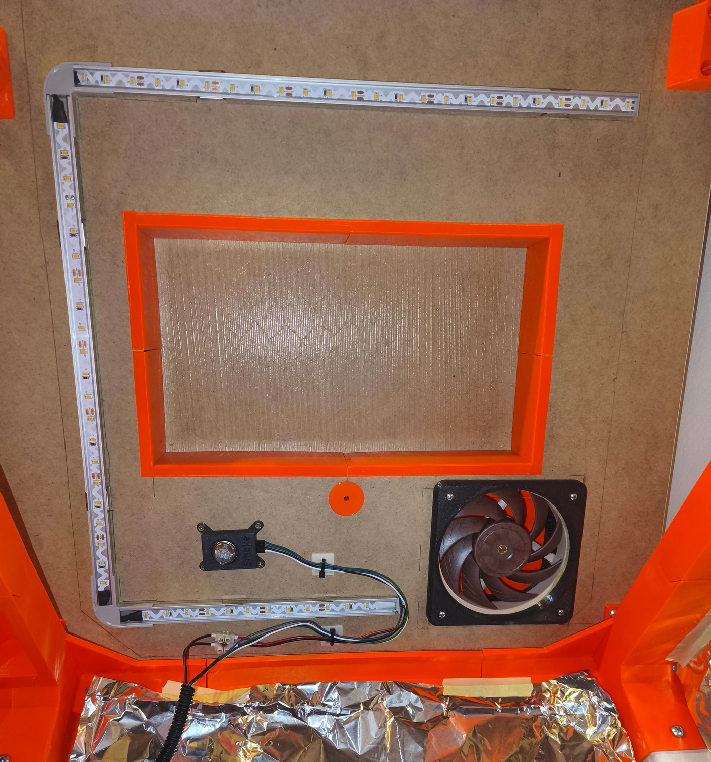
To be more specific, I printed the Vents and gears.stl and Main Support structure (not definitive).stl from this resource. I placed the structure with my ventilation fan to the rear right corner of the lid of my enclosure and due to that placement, I couldn’t use the provided Inlet Cover.stl, because it was too big and I would be unable to close the lid then. So I modeled my own inlet cover, which is on picture above and can be downloaded below. I also modeled my own stand for the servo driving the fan doors, since I had mounting issues with the one provided. It is also for download below. But first, some more pictures:


And here is the promised download:
Fire safety system
3D prints used in “fire safety system” comes from Prusarduino Nano – Fire Safety System for 3D Printers (evolved) created by Egon Heuson.
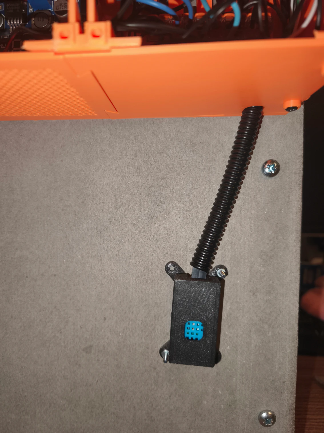
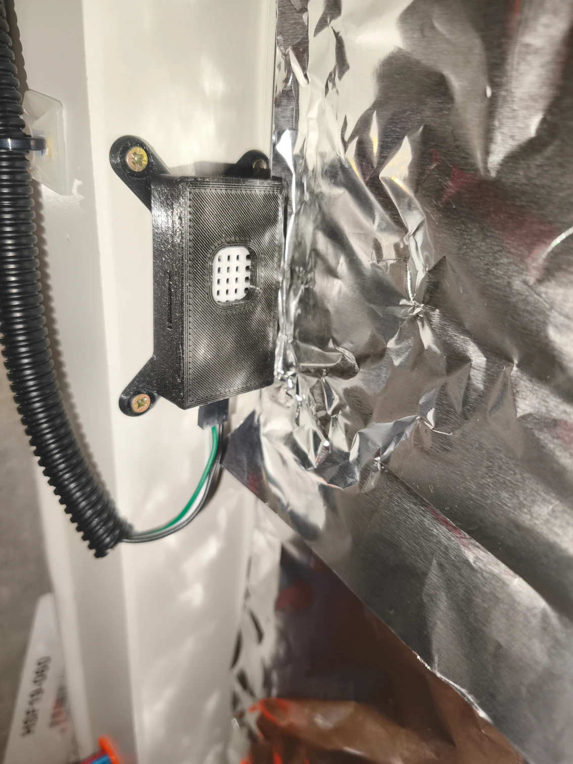
I used just some files from this project. Frankly speaking, just the enclosures for the sensors. The DHT22 case for my DHT22 inside temperature and humidity sensor, the MQ2 case for the MQ2 gas sensor and once again the DHT22 case for the DHT11 outside temperature and humidity sensor.
If I recall correctly, I think the unmodified DHT22 case actually fitted my DHT11 sensor perfectly.
Than I think I had to slightly scale the case for the DHT22 sensor. Maybe the dimensions of the boards are not exactly the same everywhere in the world, or in every series, or I may just have ones from different no-name supplier than Egon Heuson had.
The MQ2 case fitted perfectly, I think.

But, I also modeled “inserts” for the mentioned sensors, to help fix them in the cases, otherwise they were sort of floating in them hanging on the cables.


And here you can download the inserts, and the print project with scaled DHT22 sensor case:
Control panel
I designed the control panel from scratch (even though other projects that I looked at helped to shape the idea). It consist of several parts. The biggest one is the housing, which is designed to fit the edge of Ikea Lack table desk – ie. the top cover of our printer enclosure. Then there is a front panel – in which you mount the electronic components, handle (print two of them) and speaker holder (it helps to fix the active buzzer). Lets look at some design pictures:


I believe you will figure out how these parts fit together, it is not that hard. I am not sure exactly about the screws I used, but I think it was M3 to mount the front panel to the housing. I’ve put threaded inserts to plastic into the panel housing using solder. Some like these:

For the handle I think it was M2 and I screwed it directly to the plastic part.
And here is the result:

and the 3D print files:
Electronics Housing
In the first introductory article you could have seen a picture with power sources, most of the wires, Arduino UNO and other electronics. Arduino UNO, all the wires to it, power source and couple of electronics boards were placed inside an orange “house”, that was shaped like mirrored L. It was divided into smaller rectangles with support columns in between them. To remind:

I knew I wouldn’t be able to print a “big house” for the electronics and I even didn’t want to design “one time use” one and then slice it into smaller parts for printing. So I designed a modular system, that consists of smaller rectangular boxes. The box have walls (sides), bottoms, ceilings and support columns. These are designed so the boxes can be placed next to each other to form larger box(es) with various bottoms, walls and ceilings.
I made two sizes of the boxes. One is 13x12x7 cm – in this one is the silver power source on the photo above. The other is 19x9x7 cm. This one forms the “big box” section – which is assembled of six of these smaller boxes.
The idea of modularity is that each box has a base, which is rectangular frame. In each corner, a column can be placed and there are two holes to mount (screw) the base to some other structure below. In the middle of each side there is a specially shaped engraved locking hole. For these, there are locking inserts that allow to fix two bases together. The is also an insert with handle or just masking insert that will hide the respective locking hole.
I’ve also made 3 base inserts – a parts that fits exactly in the middle of the base frames and lock within the locking holes. One is for mounting Arduino UNO board, one has holders for WAGO terminal blocks and the last one allows to mount the 5V relay board for the ventilation fan and the PWM board for the LED stripe.
I also made double and quad-columns. These can be placed in between two, four base frames respectively. Along with key frame locks they allow to build pretty solid “bigger box”.
Then there is a variety of side walls. Some are plain, others have holes for routing cables or doors for access to Arduino ports. Some are to be screwed to the box columns and some are with locking-holes and some with respective locking-keys. And there are of course top covers, for both 13×12 and 13×9 boxes.
Hope it will all make more sense from the gallery below. You can see most of the parts also on the above photo.


And below, you can download the STL files and the source project, in case you need to model something that I did not create:
Holder for the Prusa printer power supply
On the photo in the above “Electronics Housing” section you can see the power source for the printer. The black one in the top right corner, mounted in orange holder.

I used the MK3/MK4 black PSU holder for Ikea Lack enclousure (rear mount) created by Matt. And again, before printing this, think twice in which direction you need to mirror / rotate the holder (if needed so for the way you will mount it) in your slicer software 🙂
Downloads
They are spread across the article above, but here, all the files in one archive:
That’s all folks
… don’t worry, just for today. Another episode is in writing and it will cover the wiring. But I can’t promise when I publish them. I am again putting this together like “half a year” back.
Links
The Prusa tutorial on building an enclosure from Ikea Lack table:
Used software:
Another projects used when printing parts for the enclosure:
- Prusa Enclosure V2 – MMU2S
- Long Lockable MMU2S Enclosure Hinges & Knobs
- Better removable Prusa Enclosure V2
- Prusa i3 MK3 60 degree heatbed cable cover
- Spool holders with ptfe coupler PC4 M10
- LACK V2 Spool Cylinder (for MMU spool holder bearings)
- Spool holder and drybox for Enclosure V2 – with humidity sensor
- Top-mounted filament thru-port for Prusa Lack Enclosure V2
- Active Cooling System Lack Enclosure
- Prusarduino Nano – Fire Safety System for 3D Printers (evolved)
- MK3/MK4 black PSU holder for Ikea Lack enclousure (rear mount)
All episodes of the series:
- The Tale of Building an enclosure for Prusa MK4S – The Idea
- The Tale of Building an enclosure for Prusa MK4S – Printed parts – this one 🙂
- The Tale of Building an enclosure for Prusa MK4S – Wiring
- The Tale of Building an enclosure for Prusa MK4S – Programming