
Let’s break down the wiring into a few smaller chapters. May even call it chunks, which more or less corresponds to the printer enclosure functions I have implemented, one after each other. These are – The “power box”, LED stripe, Outside temperature and humidity sensor, Inside temperature and humidity sensor, Gas sensor, Ventilation Fan, Ventilation Fan Doors and Control Panel
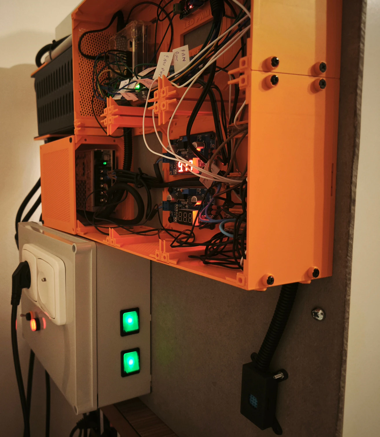
The “power box”
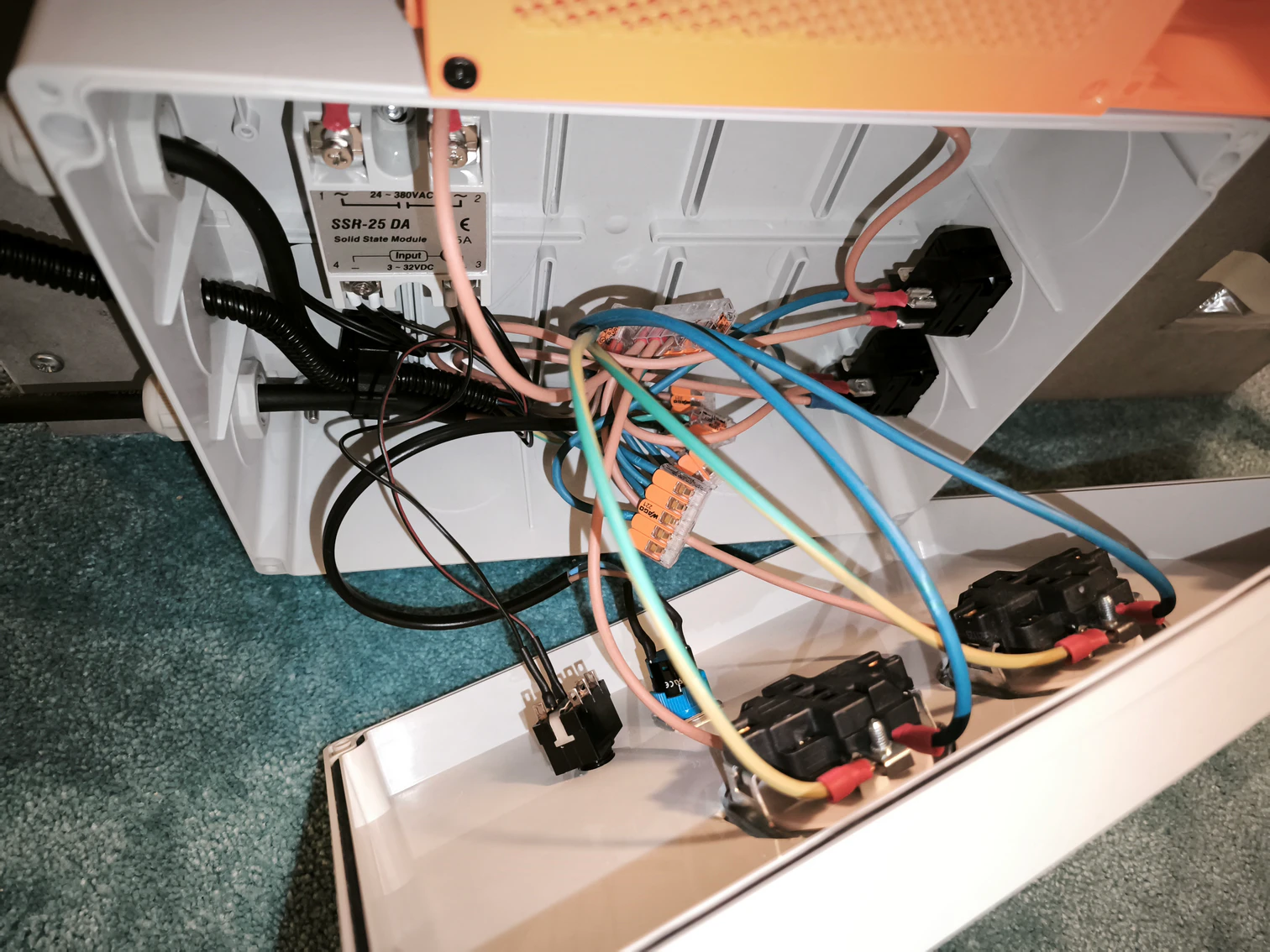
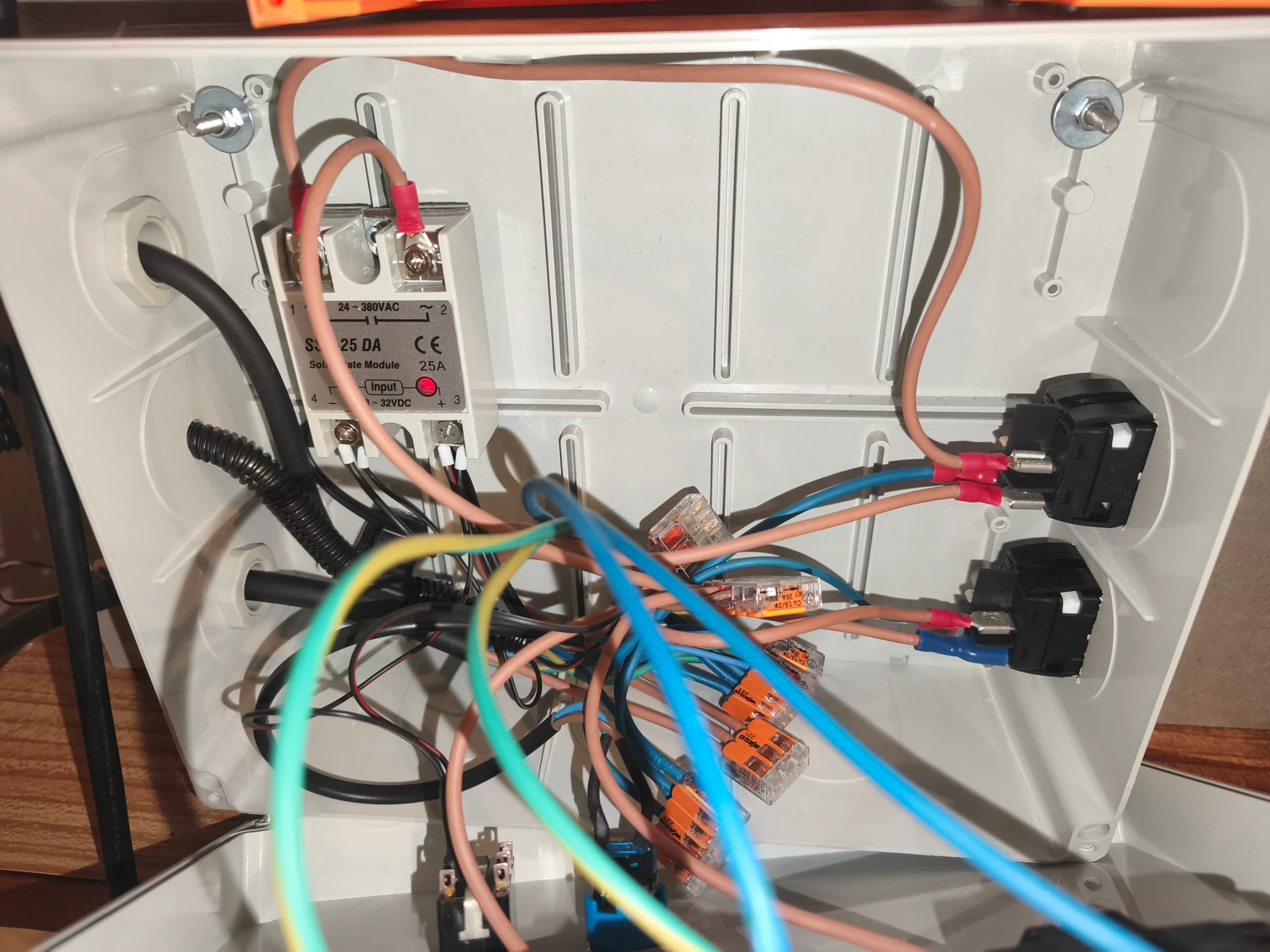
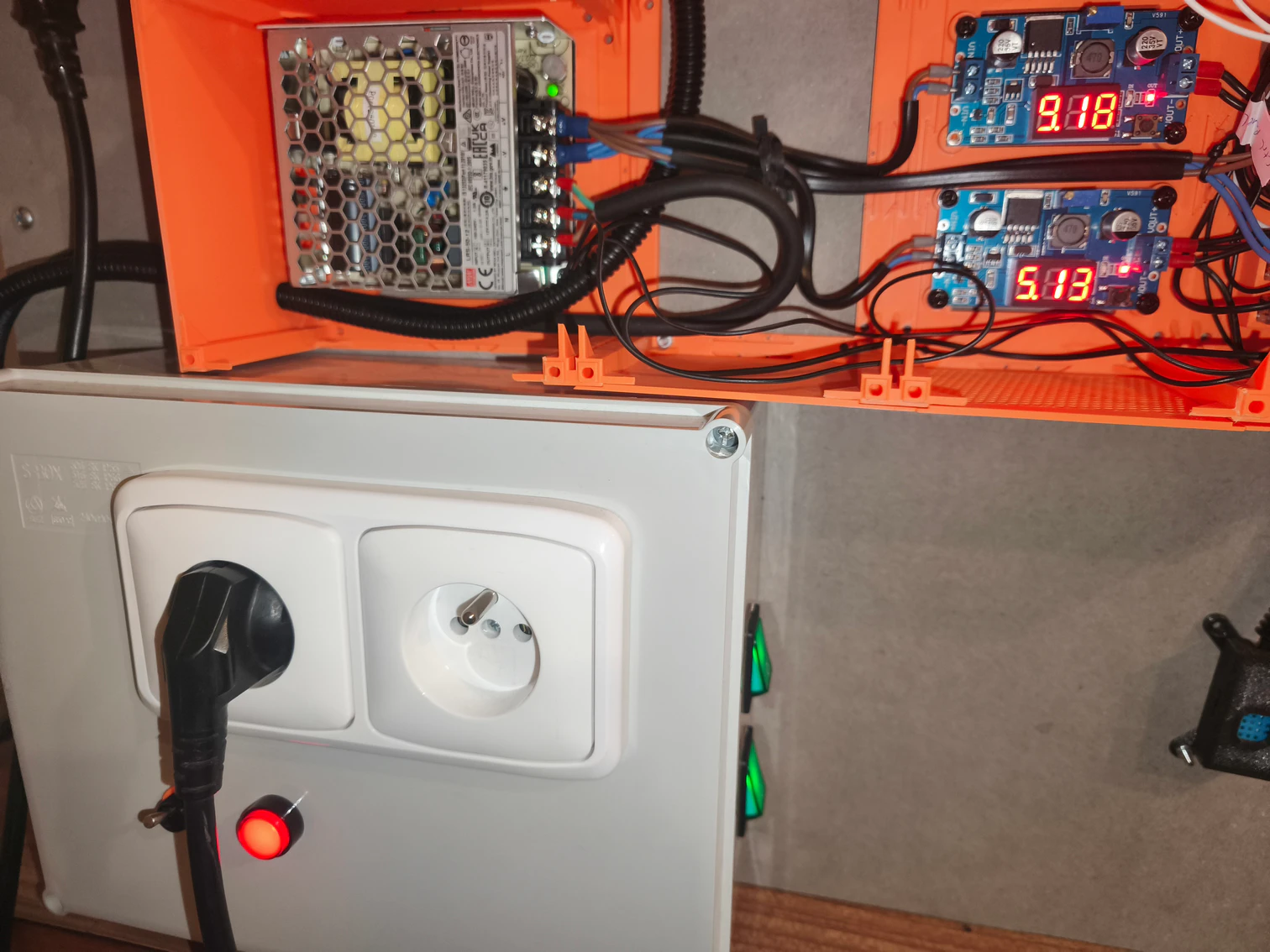
The “power box” is where it all starts to live and … then dies. Without that electrons flowing, there will be no printing… As I wrote in the introduction chapter, the enclosure control should be able to shutdown the printer in case it detects high temperature and/or smoke inside the enclosure. Here, in the “power box”, it is actually wired, among other stuff.
Warning. You should not attempt to wire this section unless you know what you are doing, neithert by following the description here. Only a certified electrician should do that! I am not guaranteeing that the circuit / approach showed here is 100% correct. The “power box” may expose you to life-threatening voltages/currents. This means it can hurt you pretty badly or even kill you!!!
The wiring on the “power box” is included here only for the sake of completeness of the description of the enclosure solution.
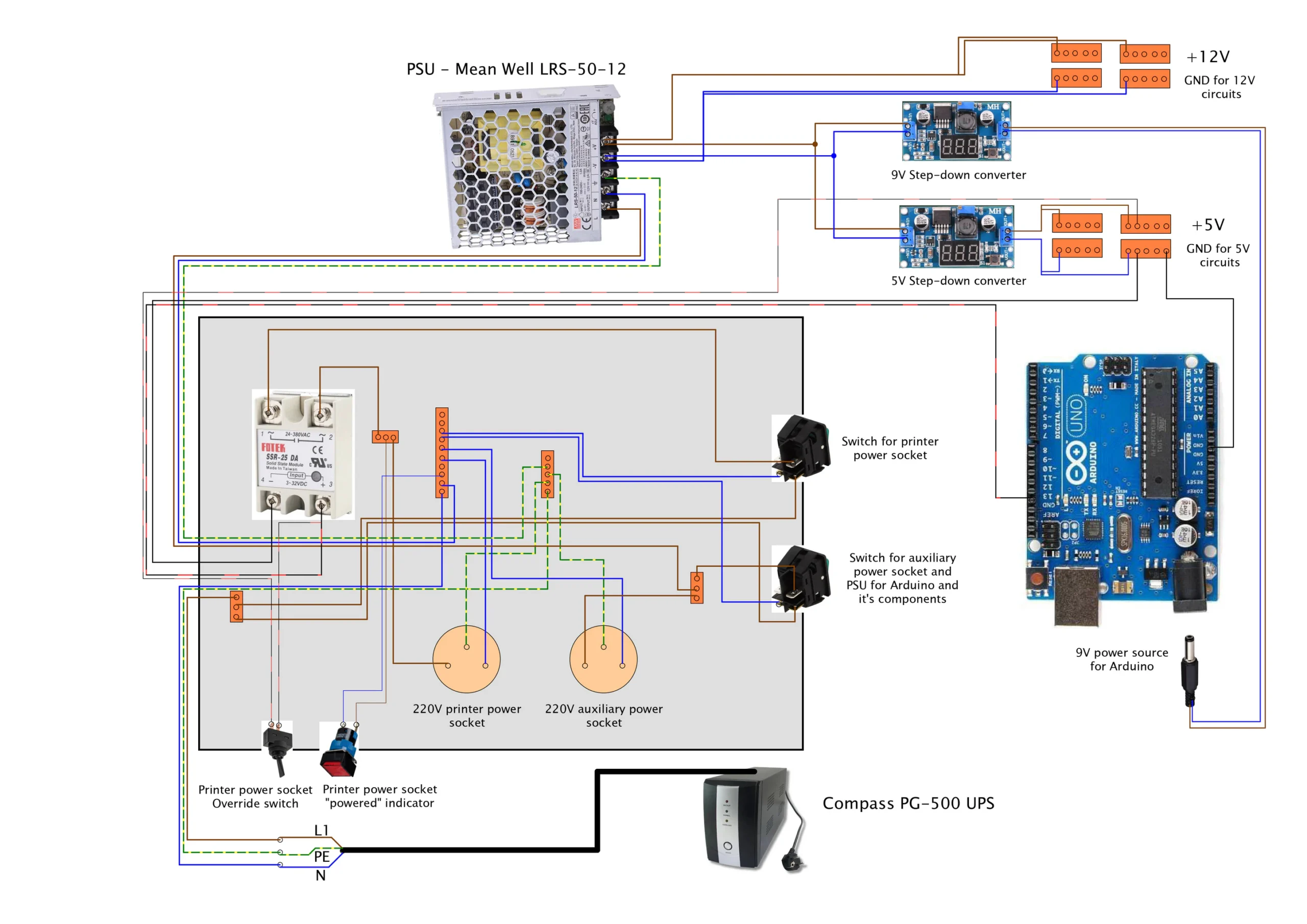
Starting at the bottom of the diagram, you can see the Compass PG-500 UPS. This is the initial power source right after the wall power socket. Note that a “little more powerful than usual” UPS is needed here, as Prusa’s MK4S requires about 240W stable power supply. So, my standard UPS with one 9V battery was getting overloaded right away. So I had to use one with two 9V batteries, which can provide up to 300W.
From the UPS, here goes a CYSY 3×1.5 power supply cable to the “power box”. That is the big gray box on the picture. The box houses two 220V power sockets, one for the printer (left one) and one for teh auxiliary stuff (camera for example). Both of these power sockets are triggered on by an illuminated switch on the side – so you know when power is allowed passing through the switches.
The live wire (L1) from the cable goes to the terminal block and from there goes one cable to one of the switching terminal on each of the two switches. The neutral wire (N), goes to another terminal block which connects all the neutral wires and the same applies for protective earth wire (PE). One of the four terminals on each switch (can’t tell exactly you which one, you have to find out for your switch, in my case, it’s the one parallel to the terminal where input live wire is), is connected by blue wire to the neutral wires terminal block – this will make the switch illuminate when pressed ON and electricity passing through it.
The live wire connected to the output terminal (the one active when switch is switched ON) of the auxiliary power switch (the bottom one) is connected to another terminal block. This terminal block connects the cable with live wire for the auxiliary power socket (the one on the right) – with it’s left “hole”. Live wire goes on the left, at least here in Czech Republic. Neutral wire goes from the right hole of the power socket and to the neutral wires terminal block. Protective earth wire goes from the pin of the power socket (the one above and between the left and right hole) to the protective earths terminal blocks. Wiring of these two wires (N and PE) is the same for both of the power sockets.
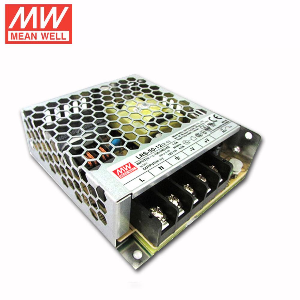
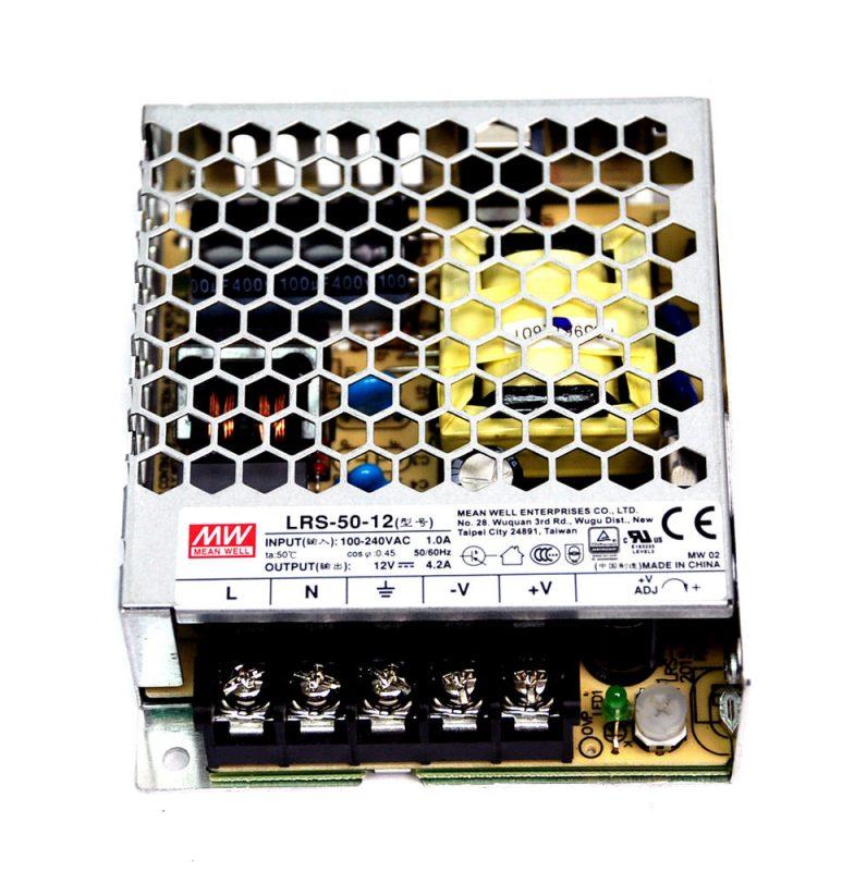
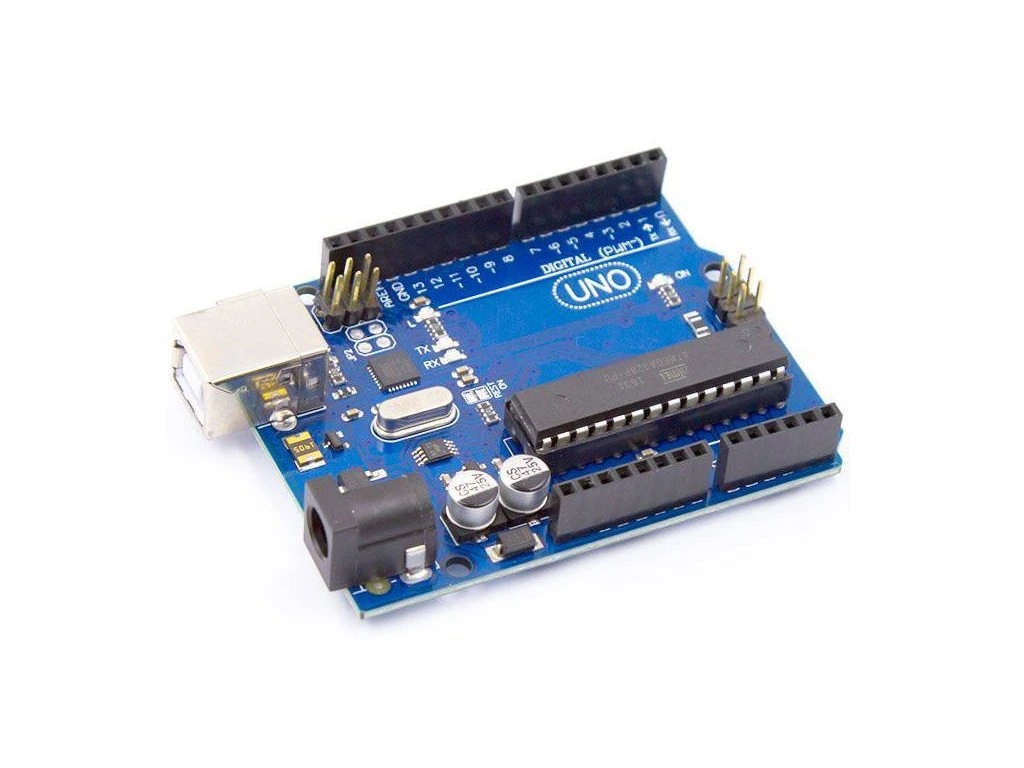
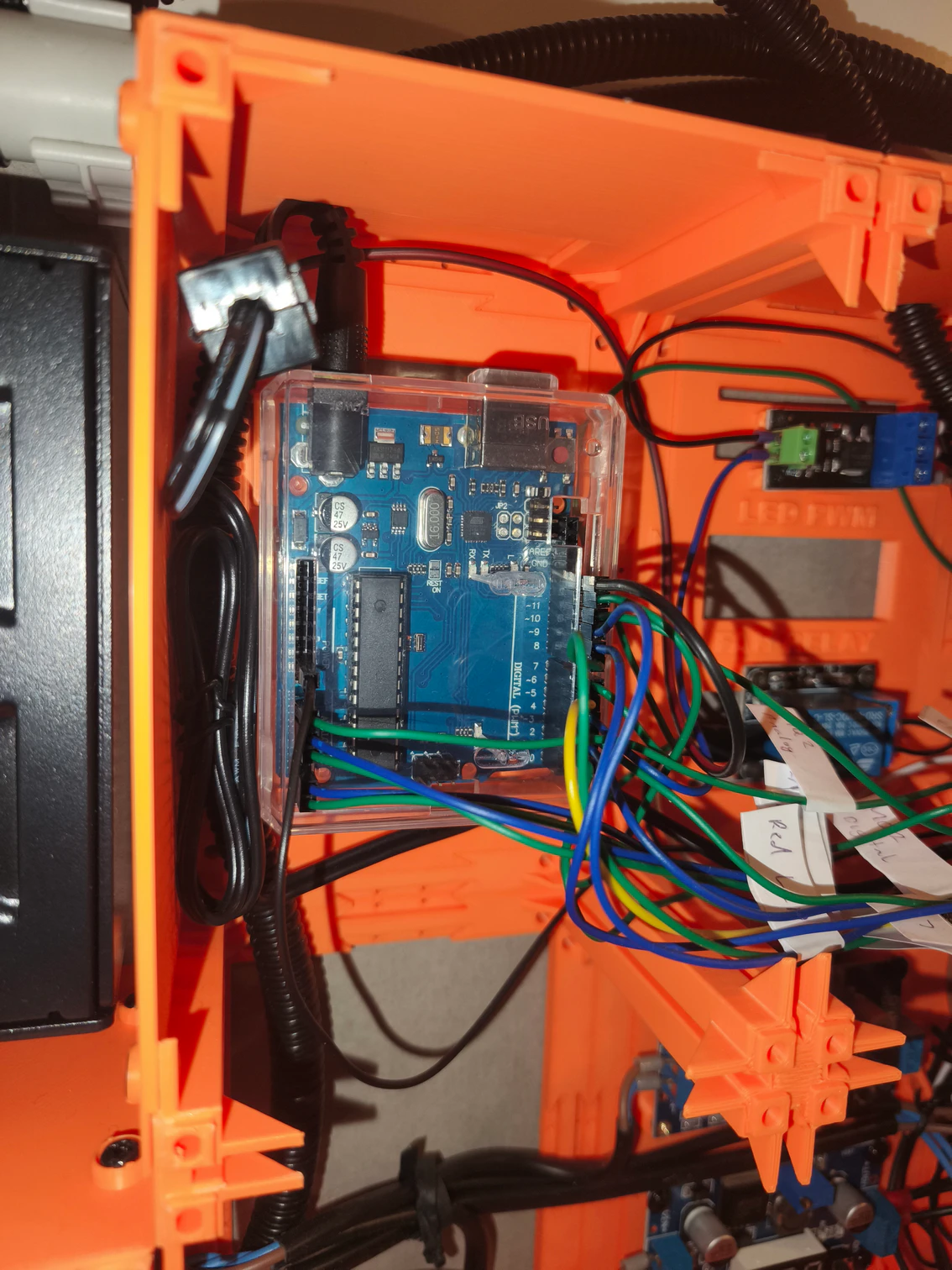
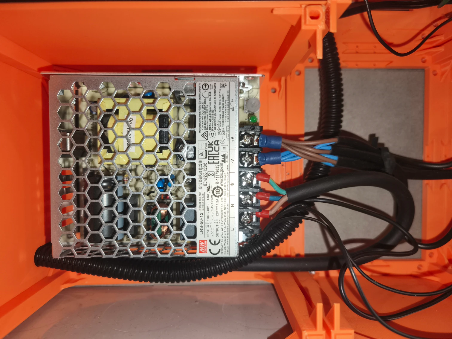
Another live wire that is connected to the same terminal block as the live wire for the auxiliary power socket, is part of another CYSY 3×1.5 cable that is connected to the live wire terminal of the Mean Well LRS-50-12 switching power supply. The another two needed wires – N and PE are connected to respective terminals on the power supply and to respective terminal blocks in the “power box”, that is kind of straight forward. The Mean Well LRS-50-12 provides power to Arduino UNO and all its connected components. It is connected to the auxiliary power sockets because we need that stuff to have power even if power socket for the printer is off.
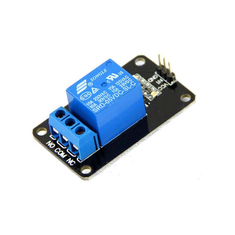
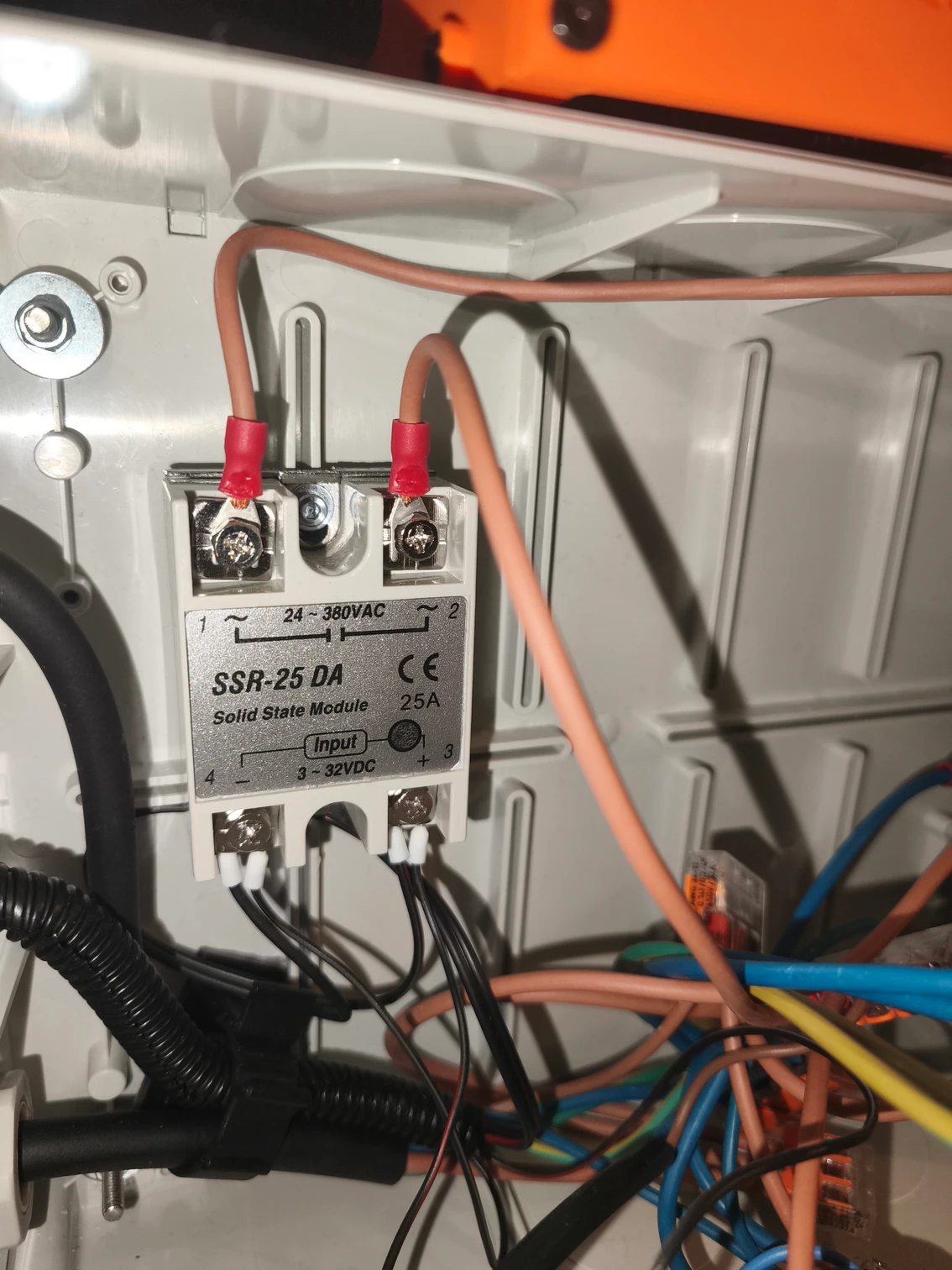
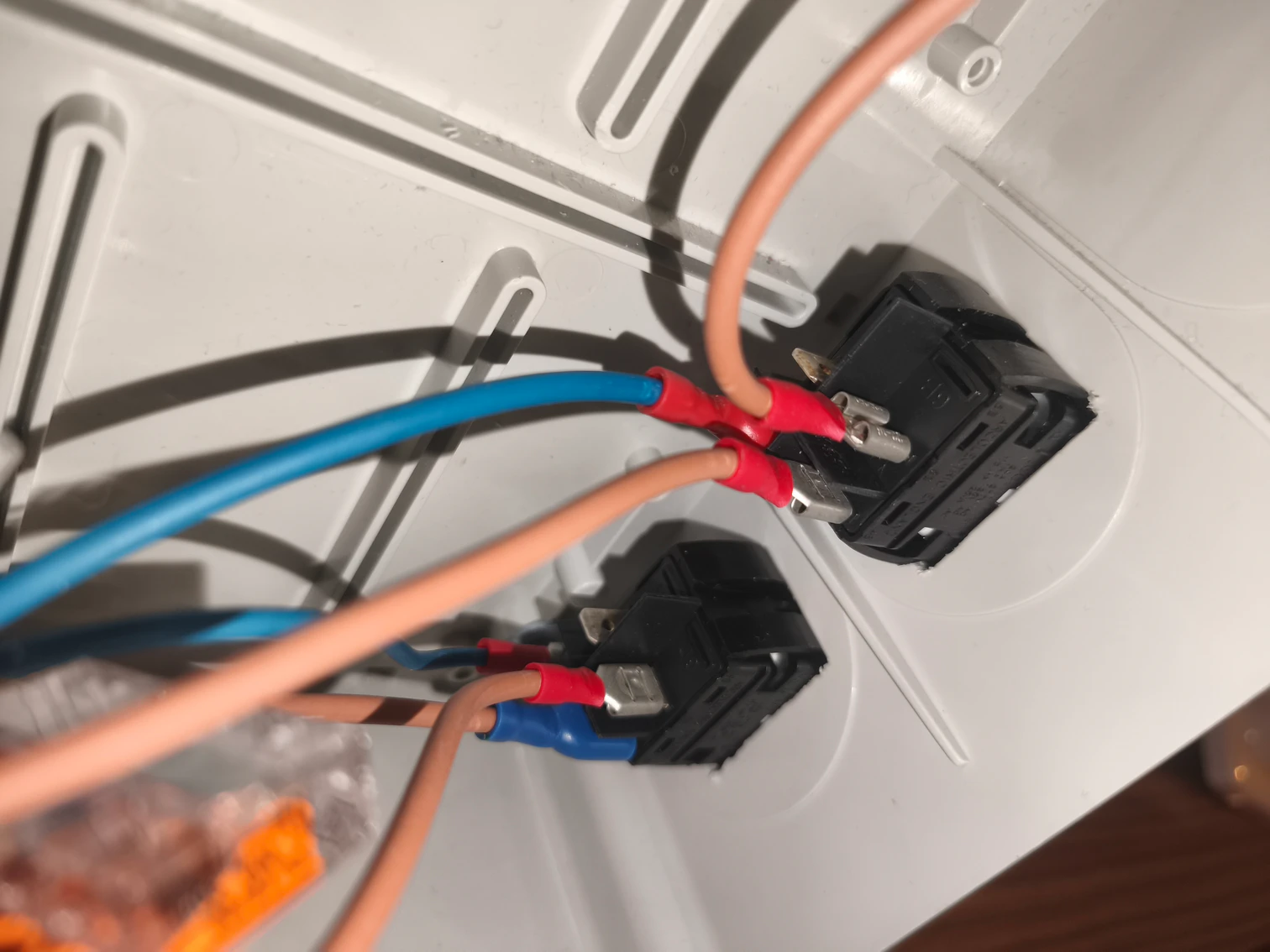
Now for the printer power socket. The live wire connected to the output terminal (again, the one active when switch is on) of the top switch, goes to the terminal 1 of the SSR-25-DA. That is solid state relay. The relay is here because we need the Arduino UNO to be able to “cut off” the printer from electricity in case it detects some hazardous conditions in the enclosure. From terminal 2 of the relay, an “output” live wire goes to another terminal block. From this terminal block, there finally goes a live wire to the left “hole” terminal of the printer power socket. It is clear where does the the N and PE wires of the printer power socket go, I hope 🙂 You can see there goes another live wire from mentioned terminal block. And it goes to the terminal of 220V LED indicator. The other terminal of the indicator is connected by blue wire to the neutral terminal block. This indicator will show us, that the SSR realy is switched ON and thus the printer power socket is powered.
The SSR relay is controlled by 5V signal from Arduino board. Trace the lines on the diagram and you will find out, that the minus (-) terminal of the relay is connected to the ground terminal block of 5V circuits (Arduino UNO board is connected to this terminal block too). The plus (+) terminal is connected to PIN 13 of Arduino UNO, which then controls the SSR relay. For the sake of debugging my Arduino controller “firmware”, I added an override switch to allow me to bypass Arduino switching off the printer power socket because of some silly software bug, causing the print to fail prematurely. The switch has on terminal connected to the 5V distribution terminal block and the other to the plus terminal of the SSR relay. So, when it is ON, the relay will be ON even if Arduino signals to disconnect the relay.
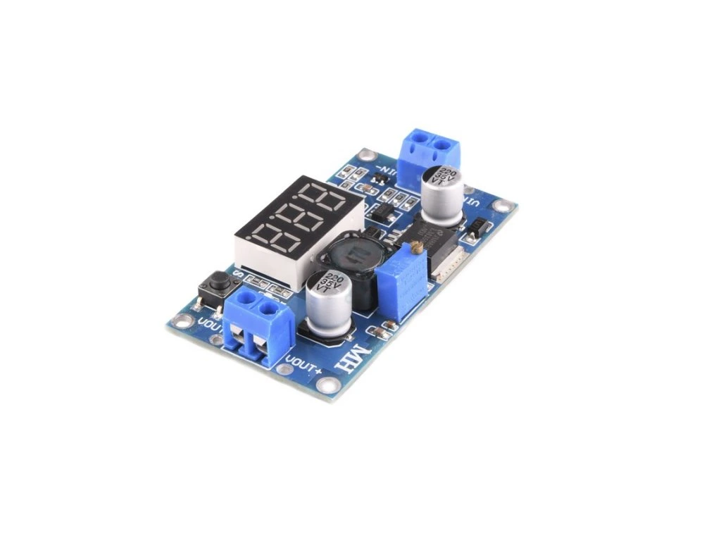
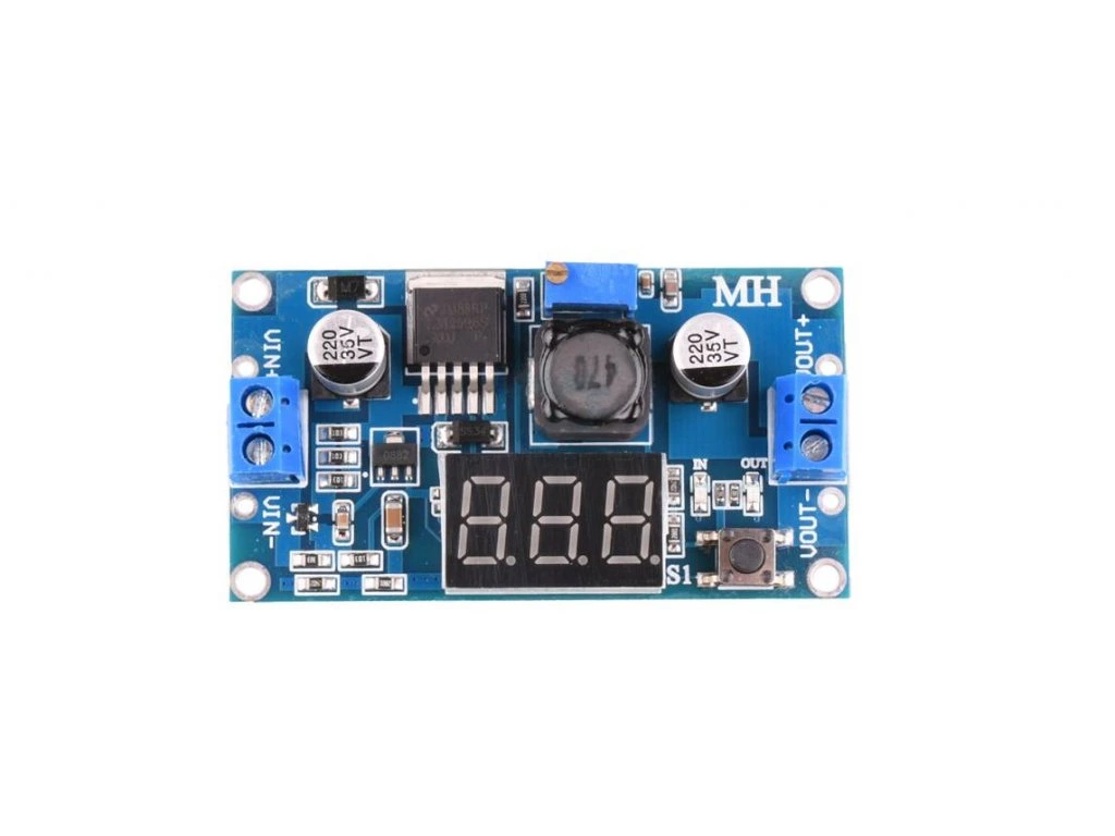
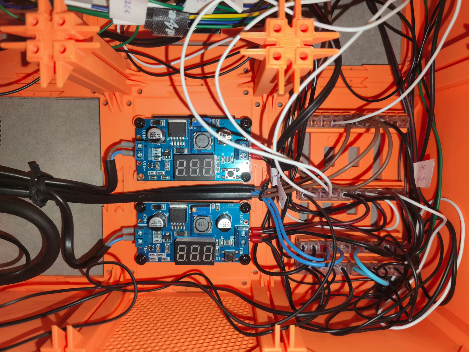
Not much left on the wiring diagram, just the stuff on the right of the Mean Well power supply. We connected the input wires, so whats left are the output wires. The output terminals – plus and minus (ground) of the power supply are connected to three places. First, the plus goes to the two 12V terminal blocks (because 12V is native output of the power supply). The minus goes to the two ground terminal blocks for 12V circuits. The power supply output terminals are also connected to the two step-down voltage converters. One lowers the voltage to 9V – this is to power Arduino UNO board (I know we can even use the max of 12V for it, but I wanted to use 9V which is what power adapters for Arduino usually use). The other lowers to 5V, which is what most of the components connected to Arduino use. The outputs of this step-down converter are connected to the two 5V distribution terminal blocks and to the two ground terminal blocks for 5V circuits. The output od 9V converter is connected straight to cable powering the Arduino UNO board.
Well, a lot of characters written, but it is not that complicated when taken step by step. Which I know is easy to say when you’ve got it done 🙂
Below is the gallery of some of the used components:
LED stripe
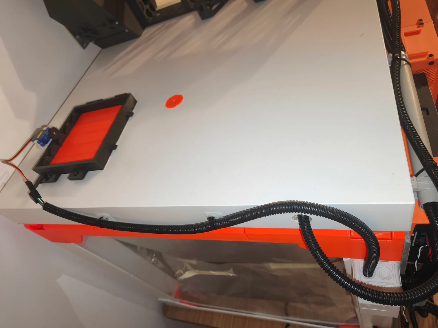
Enclosing the printer in the box should make it feel more comfortable temperature-wise speaking, but, on the other side, the printer may feel a little scared , with all that darkness this improvement will bring along at some point in the day. Thus, it would be nice to have a light in there… Of course we will go with nothing less than dimmable LED stripe solution.
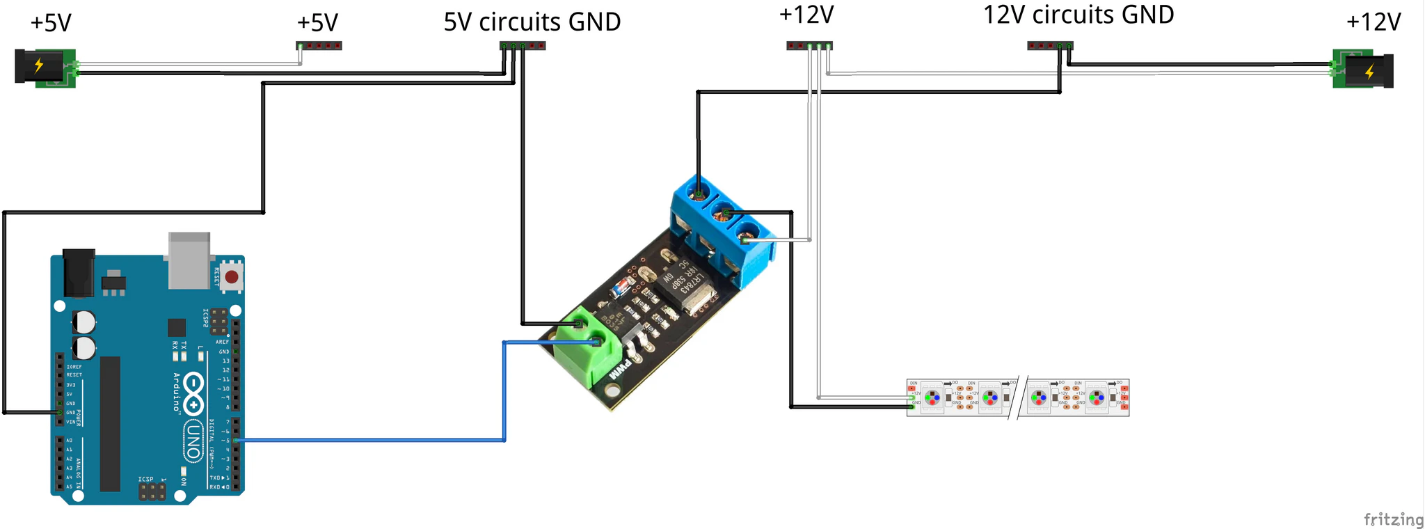
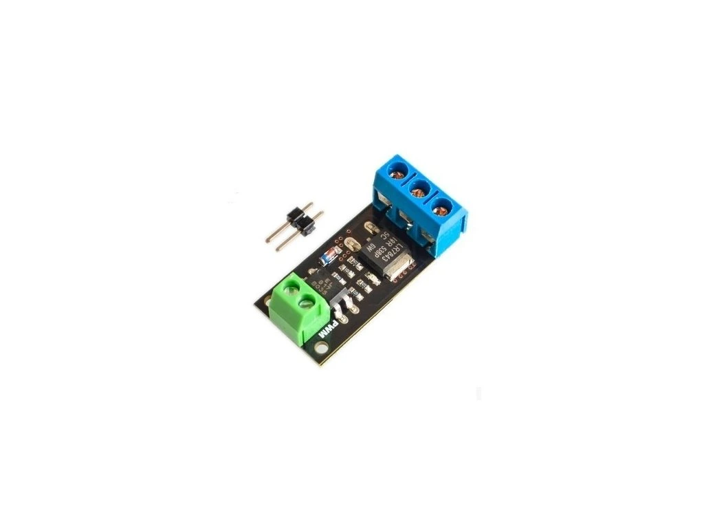
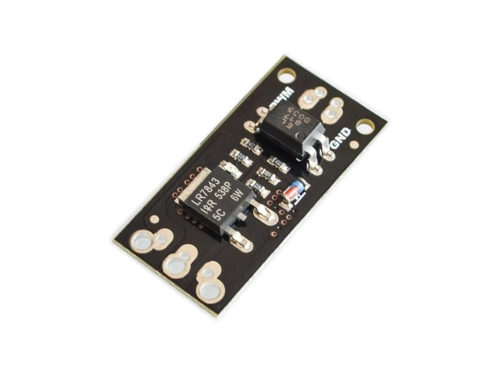
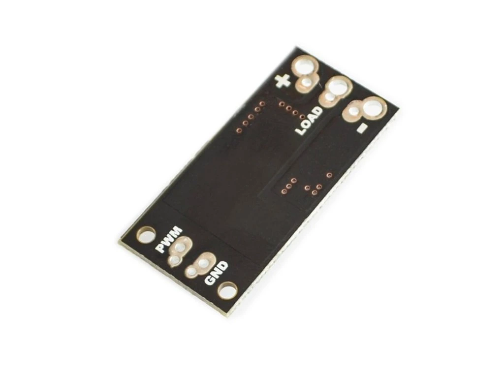
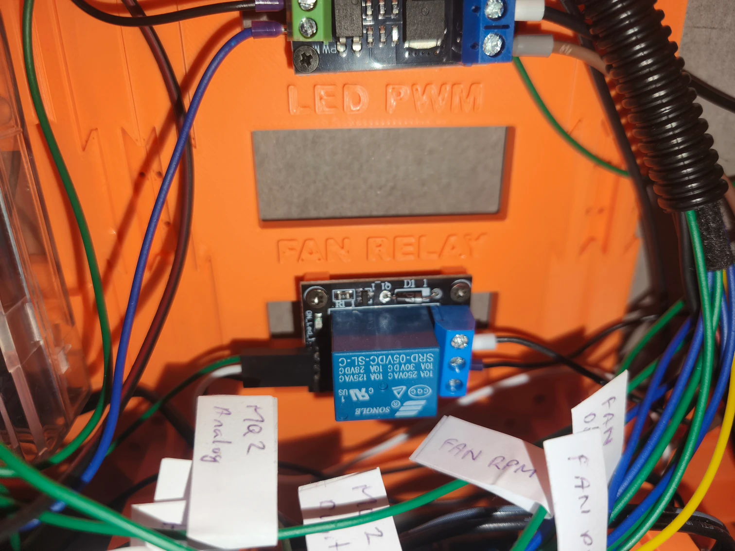
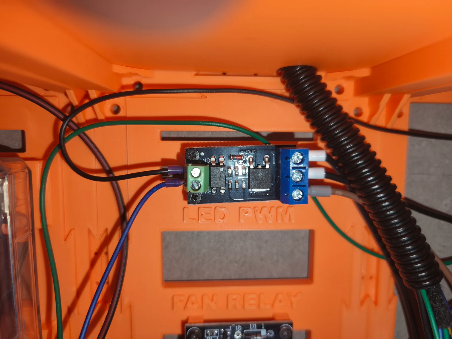
LED stripes are usually powered by 12V or 24V, so we cannot work with it directly with Arduino UNO board. From the “power box” chapter you know we have 12V power supply, so we use 12V LED stripe. To control the LED stripe, we need tu put “something” in between it and the Arduino and the “something” I used is the PWM MOSFET module LR7843. This module allows to drive large loads with PWM. So, by one side we connect it to one of the Arduino’s PWM output (PIN 5 on the diagram, connected via blue cable) and by the other to the LED stripe. The control voltage for the board is 3.3 – 5V, so exactly for Arduino. The output side of the board has 3 terminals: plus, minus and load. Connect the plus terminal to the 12V distribution terminal block. The plus contact of the LED stripe also gets connected to the same 12V distribution terminal block. The minus terminal of the module gets connected to the ground terminal block of 12V circuits and the minus terminal of the LED stripe gets connected to the load terminal of the module, making the circuit complete. The mentioned terminal blocks are the same as the ones on the “power box” diagram.
Below is the gallery of some of the used components:


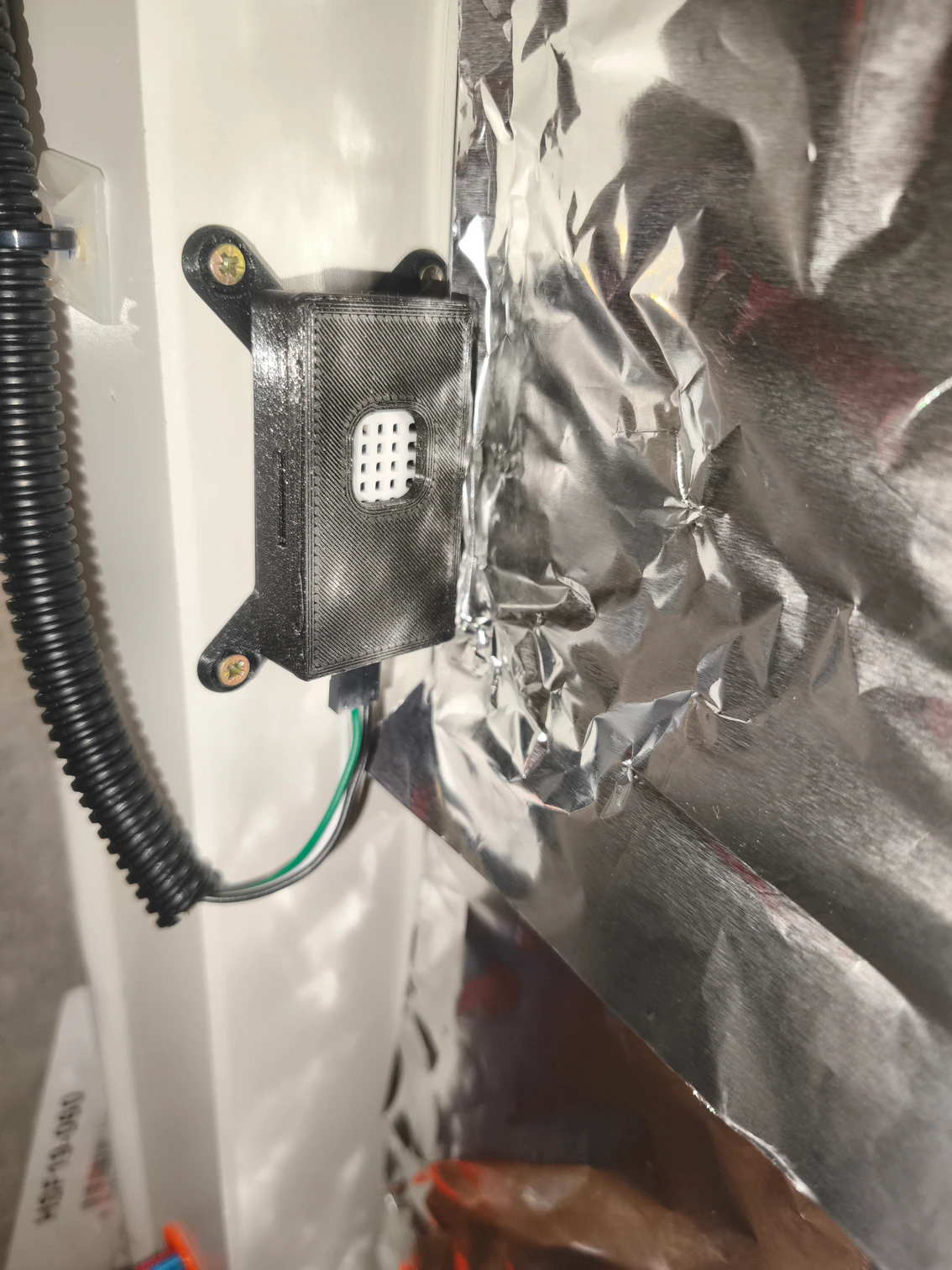
Outside temperature and humidity sensor
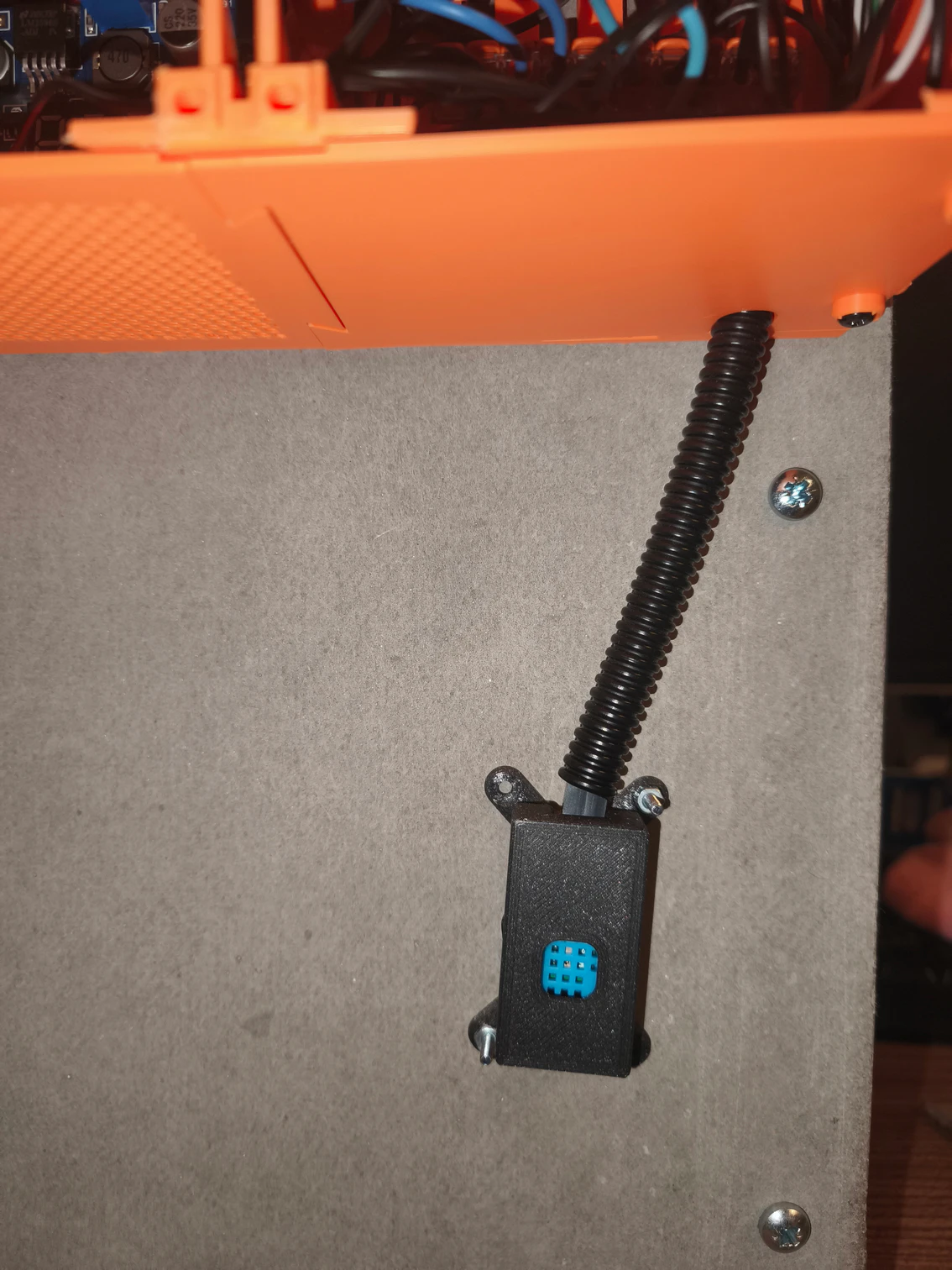
We need to know not only how is the environment inside the printer enclosure, but also, how it is outside. For the outside area, temperature and humidity will be enough. I used the DHT11 module. It’s measuring range is less than DHT22 which is used inside, but I think temperature range from 0-60°C and 20% to 90% for humidity is good enough. Should you get outside these ranges in the room where you are printing, i think it would be pretty uncomfortable for all – you, the printer and most of other currently present creatures.
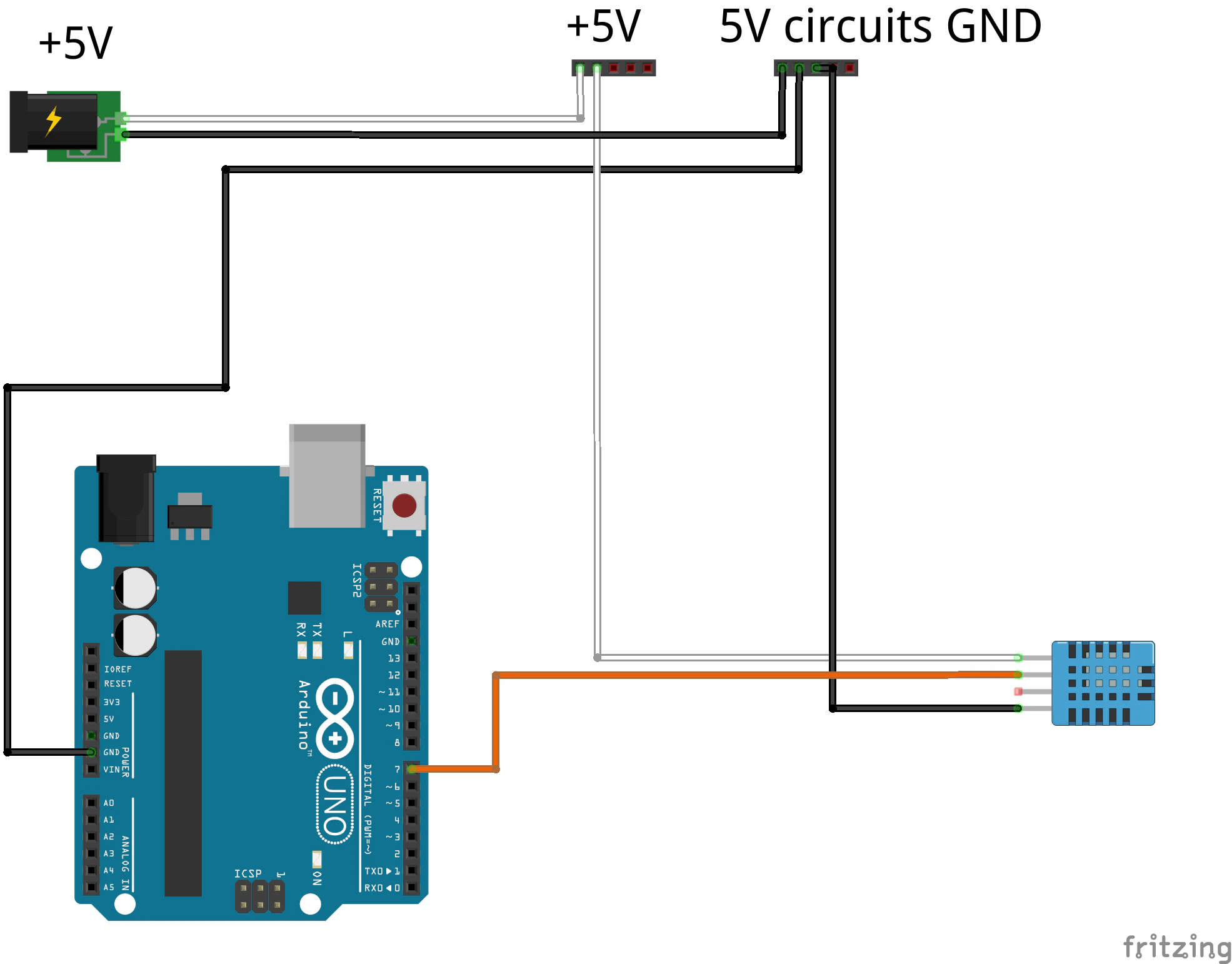
The connection is pretty easy. Please ignore that the DHT11 sensor in the diagram has four outputs, the actual used board has only three. On is plus terminal, which is connected to the 5V distribution terminal block. The other one is the minus terminal, which is connected to the ground terminal block for 5V circuits. The last one is the digital reading of temperature / humidity which is connected by orange wire to PIN 7 of Arduino.
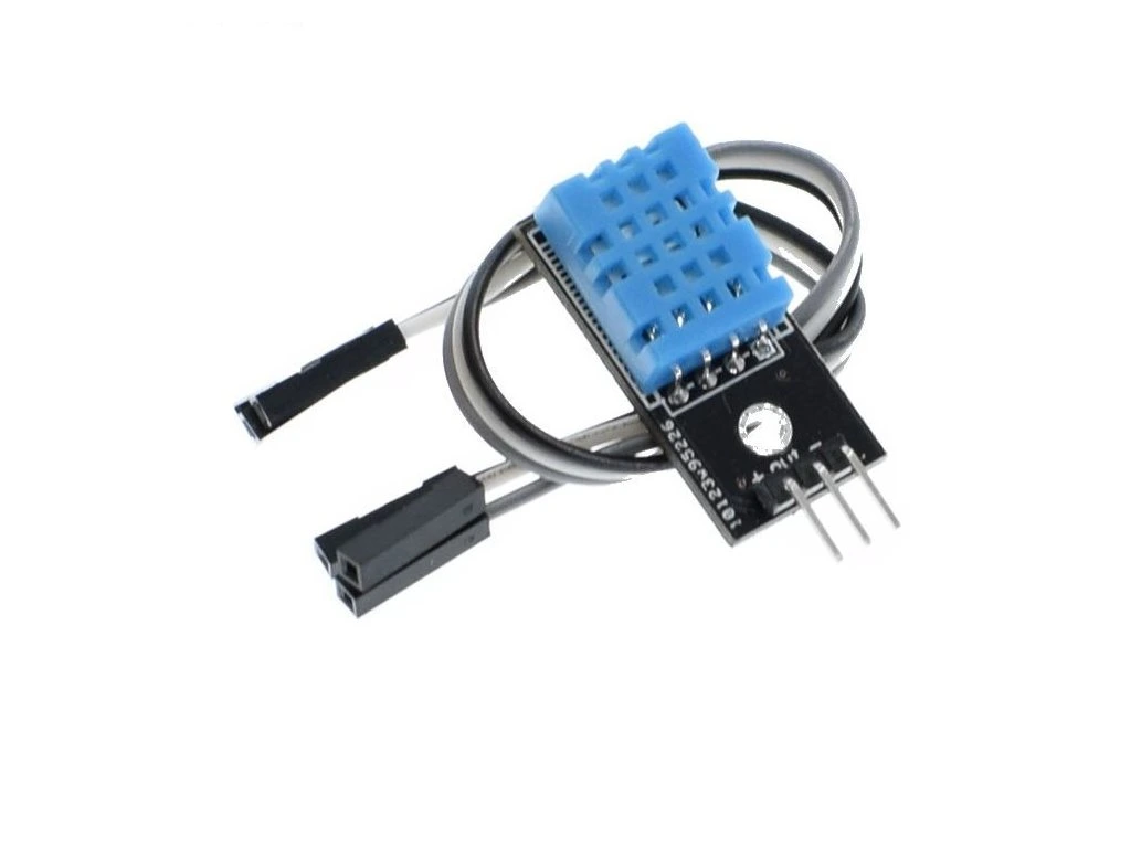
Below is the gallery of some of the used components:
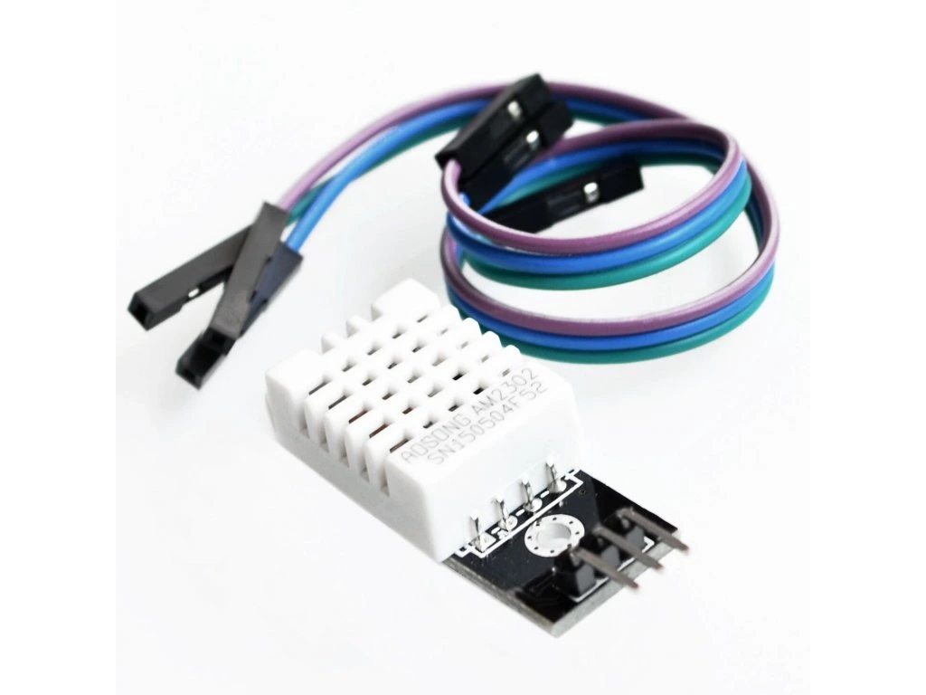
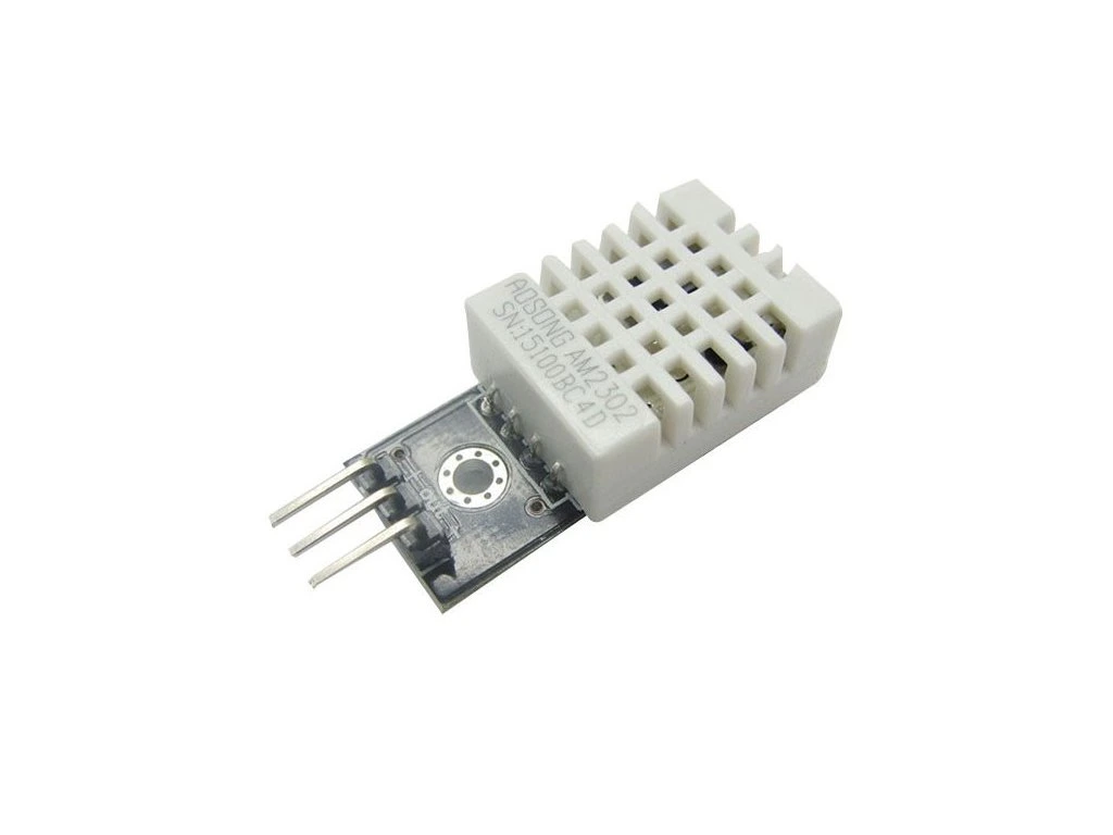
Inside temperature and humidity sensor
First of the two sensors that help us monitor the environment and potentially hazardous conditions inside the printer enclosure is temperature / humidity sensor. I used the DHT22 module as its temperature measurement range is from -40 to 80°C and up 100% for humidity.
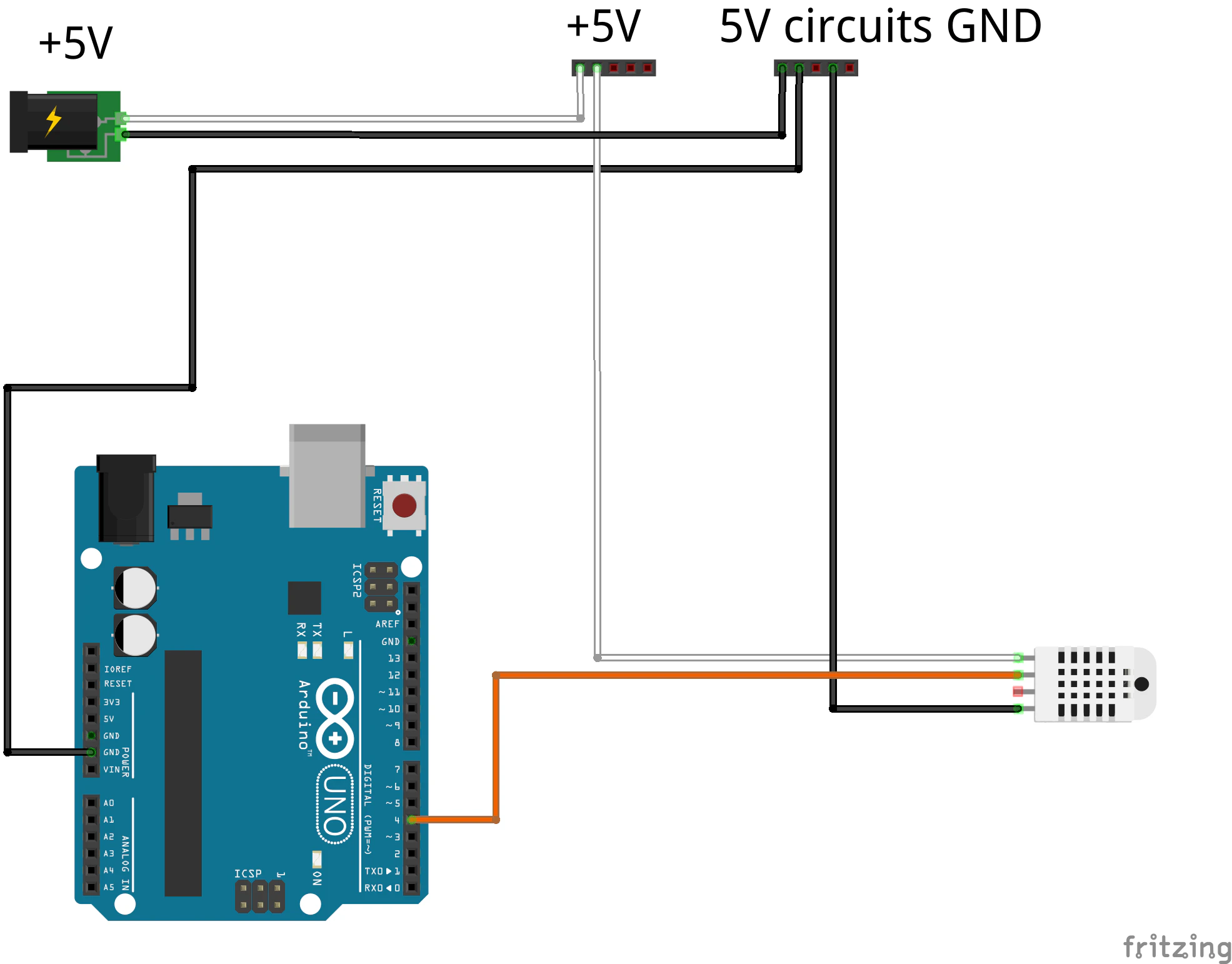
The connection of the DHT22 module is done in the same way as for DHT11. It has a plus terminal to supply input voltage, which gets connected to the 5V terminal distribution block. The minus (ground) terminal gets connected to the ground terminal block for 5V circuits. And the last terminal (I know there are 4 on the diagram, but we use board that has only 3 outputs), is a digital reading of temperature / humidity and it gets connected to Arduino, PIN 4 via orange wire.
Below is the gallery of some of the used components:
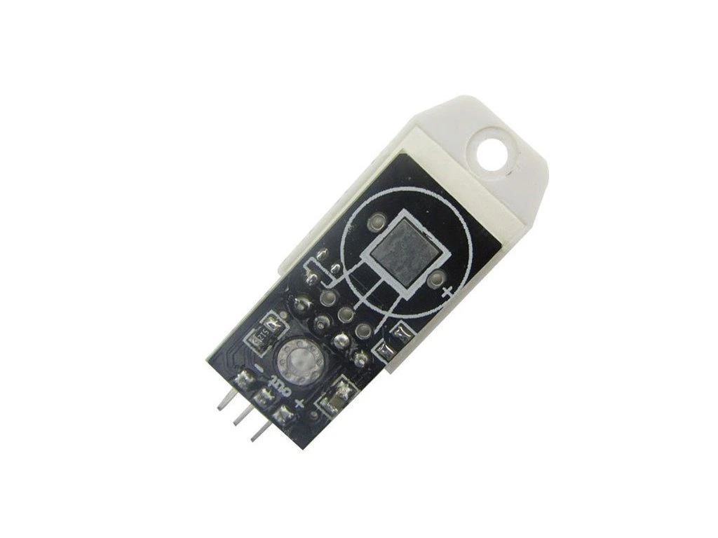
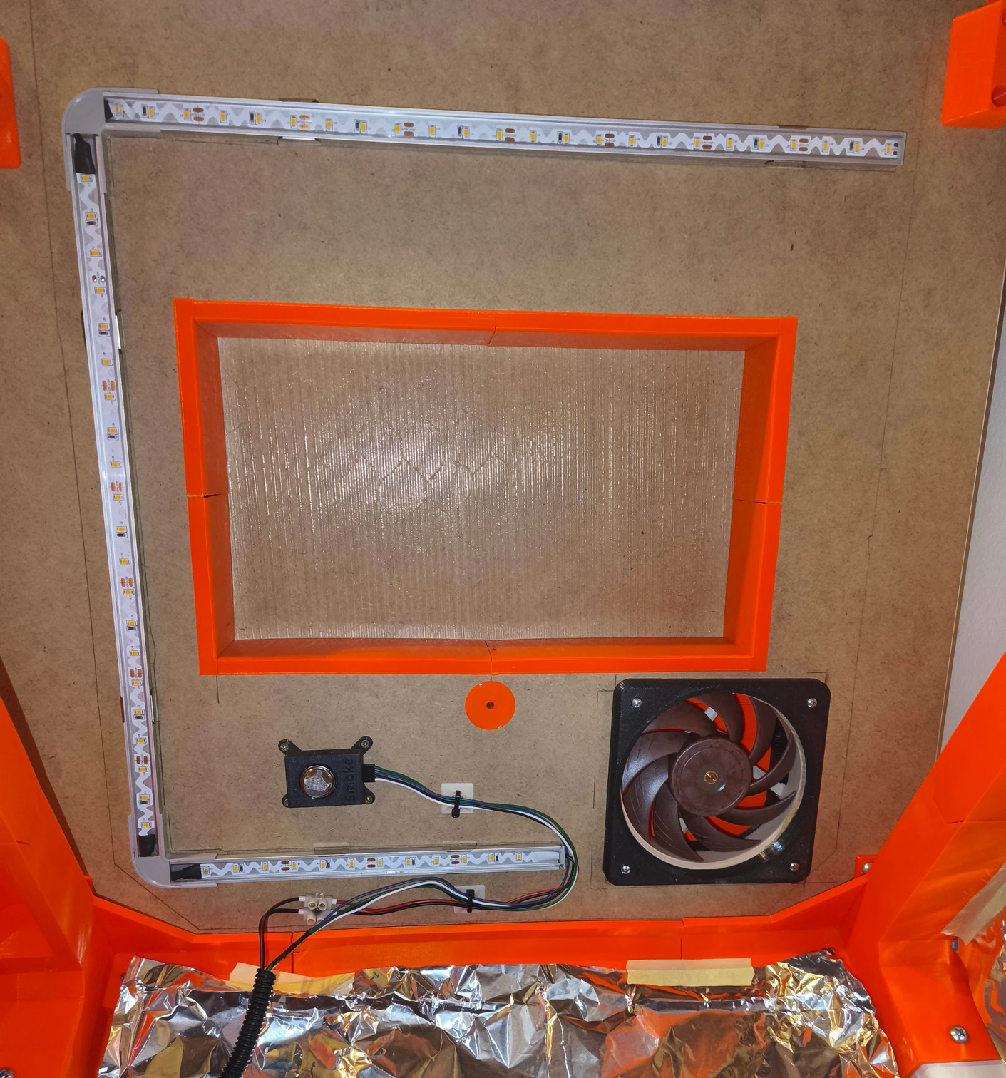
Gas sensor
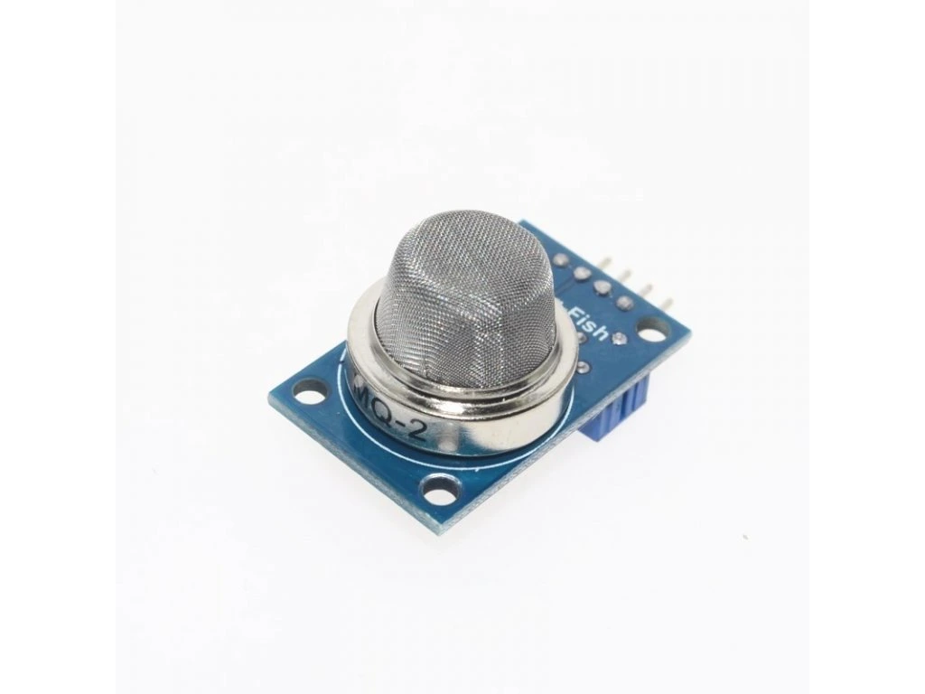
Second of the two sensors that help us monitor the environment and potentially hazardous conditions inside the printer enclosure is MQ2 gas sensor, respectively a board with that sensor that simplifies its connection and usage.
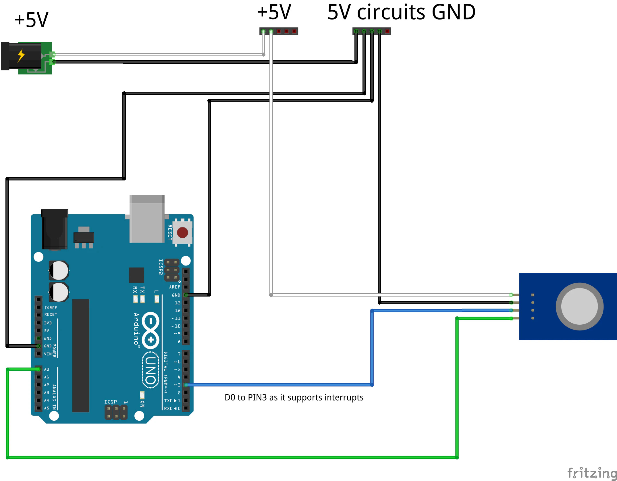
The MQ2 gas sensor wiring (when used on module board like we do) is pretty easy. We connect Vcc terminal , ie. the voltage supply to 5V terminal block. Ground to ground terminal block of 5V circuits. Then, there are two terminals left on the MQ2 board. D0 – digital output which triggers from low to high when predefined gas level is sensed. It needs to be connected to the input that supports interrupts, PIN 3 will server us good for this case on Arduino UNO (connected using blue wire). And the last one analog A0 output, which allows analog reading of gas sensor measurements. It is connected by green wire to analog PIN A0 on Arduino UNO.
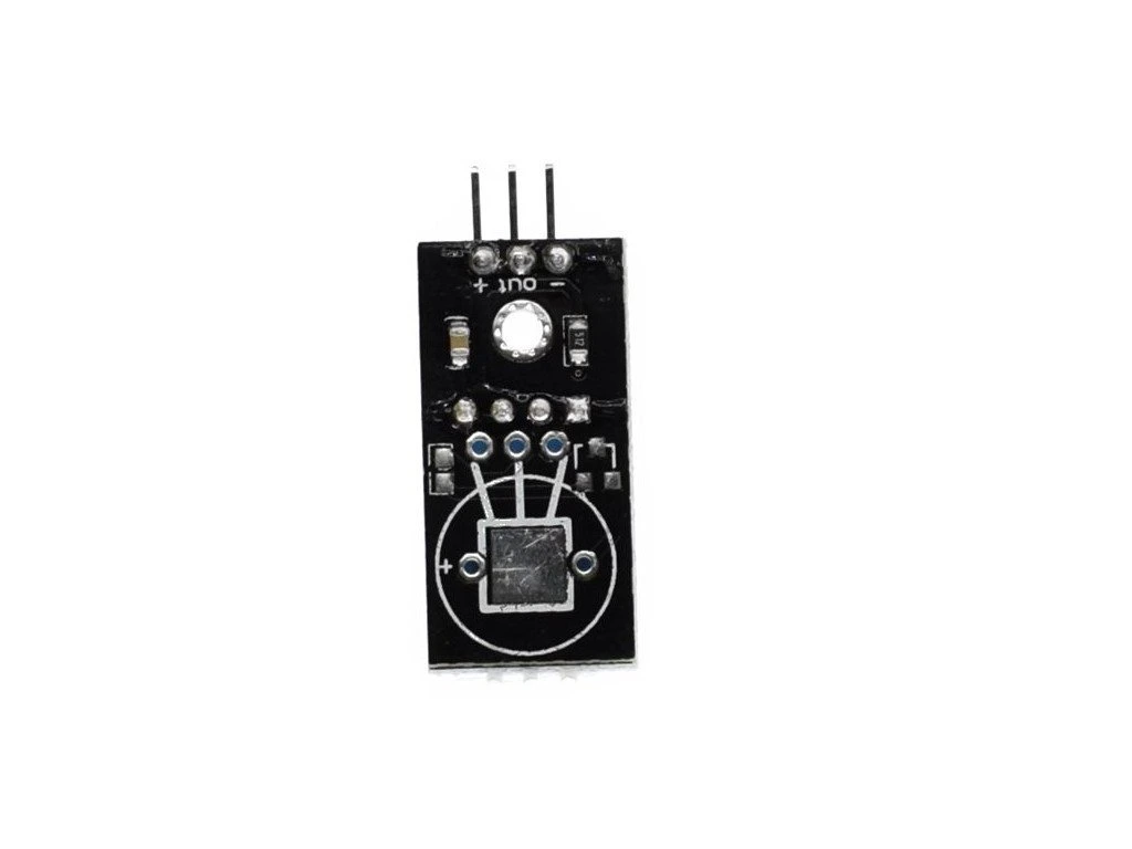
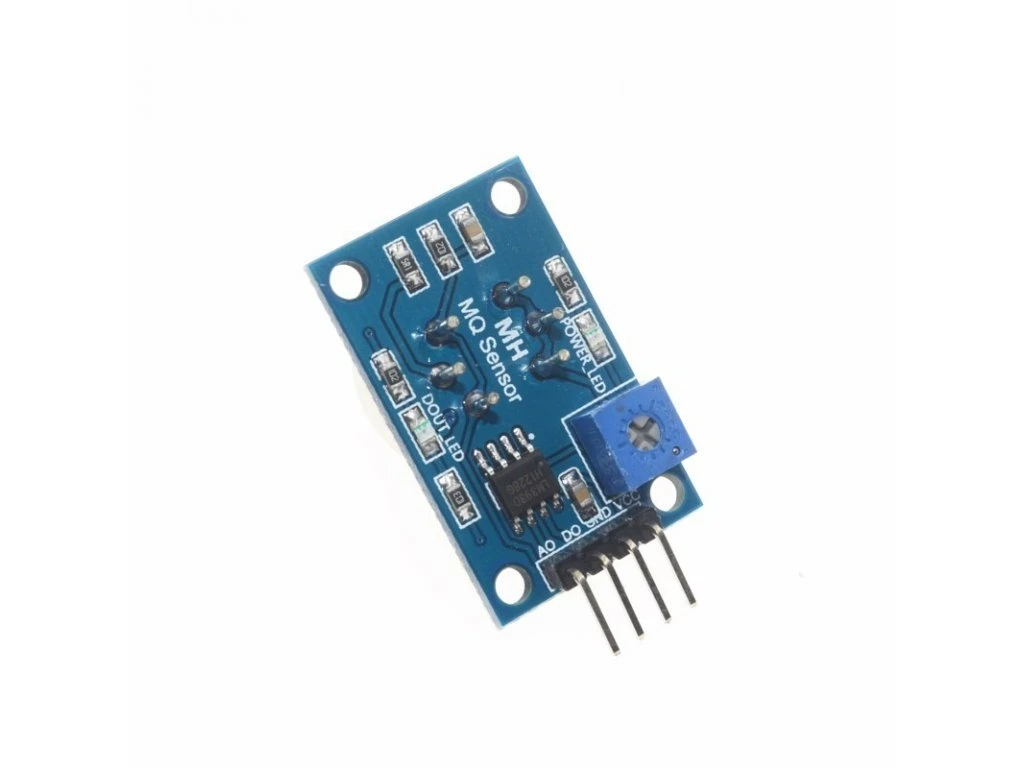
Below is the gallery of some of the used components:
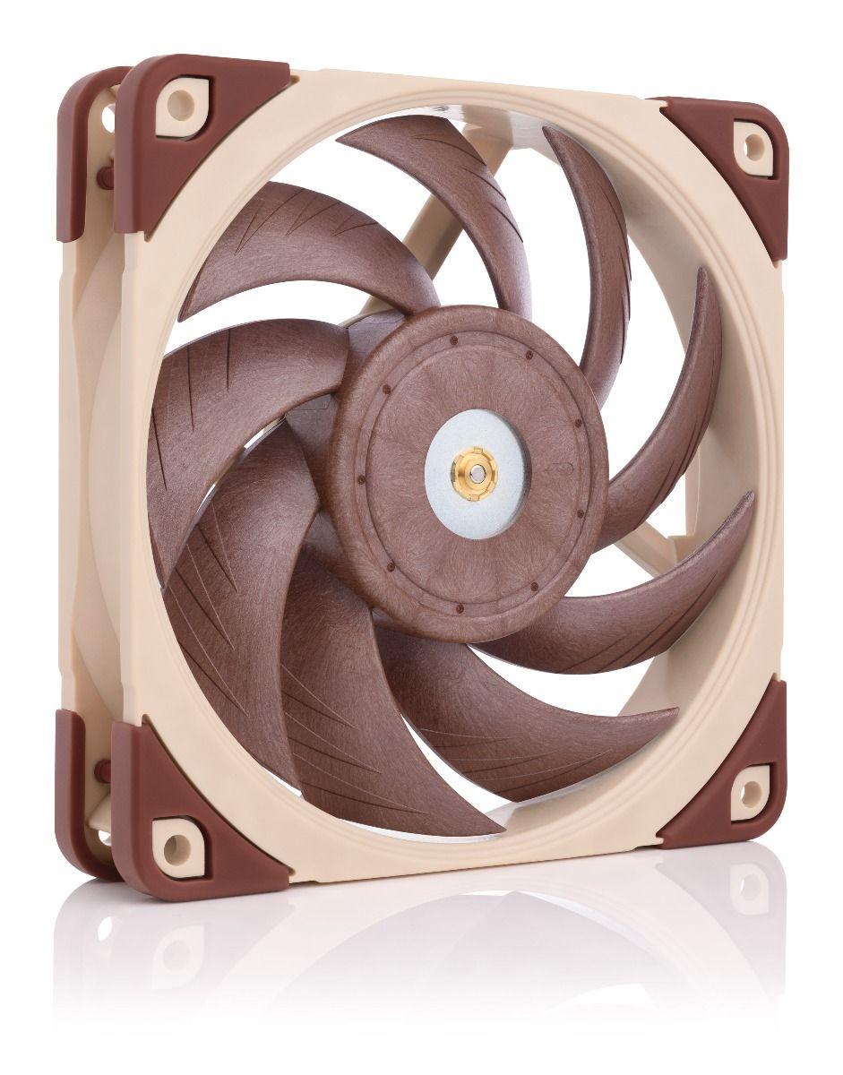
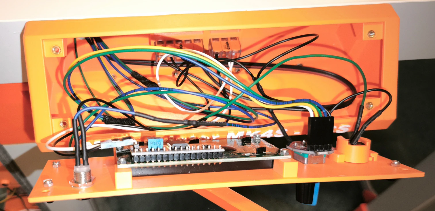
Ventilation Fan
The ventilation fan connection appeared to be a little more challenging. I couldn’t use just another PWM board or similar approach as I did in my cockpit. Or, maybe I didn’t want to, I can’t remember right now. Maybe I wanted to learn how to control fan directly by Arduino. There are lots of various tutorials for that and the control of PC fan directly by Arduino turns out to be not as straightforward as one would wish. Anyway, the wiring that worked for me and the way my Arduino code is written is on the following diagram:
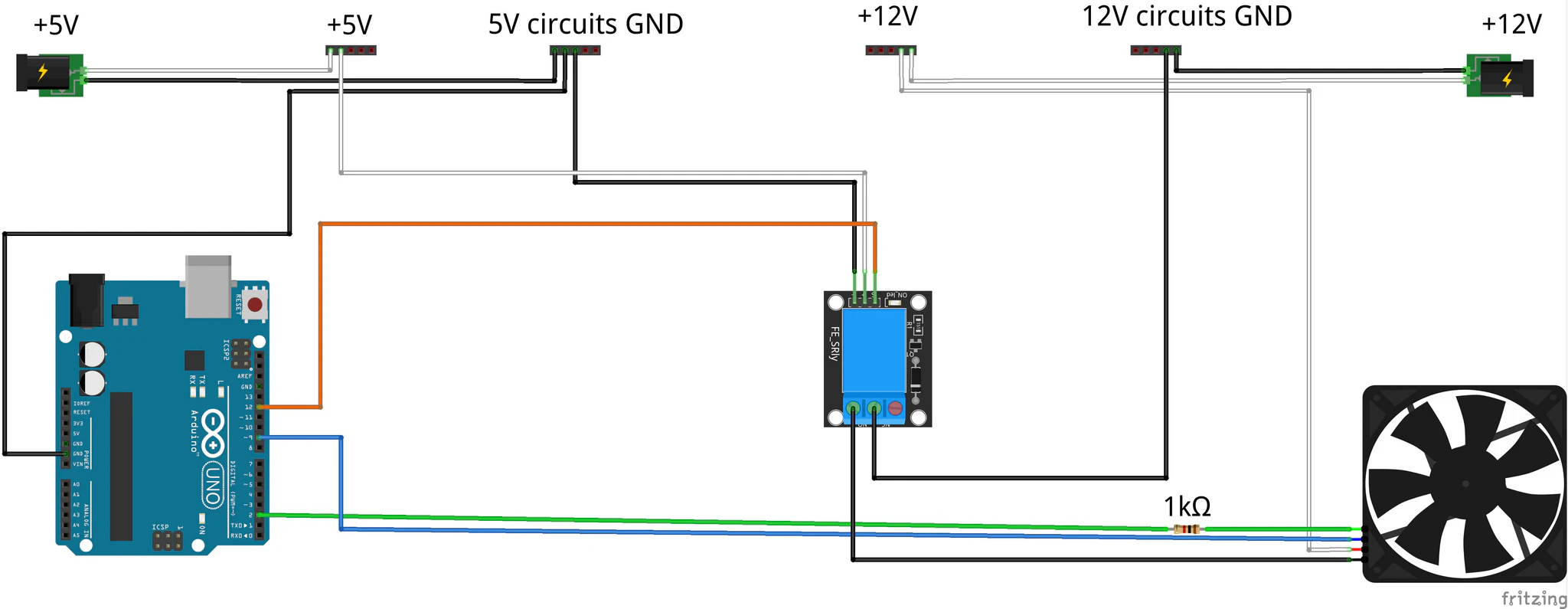
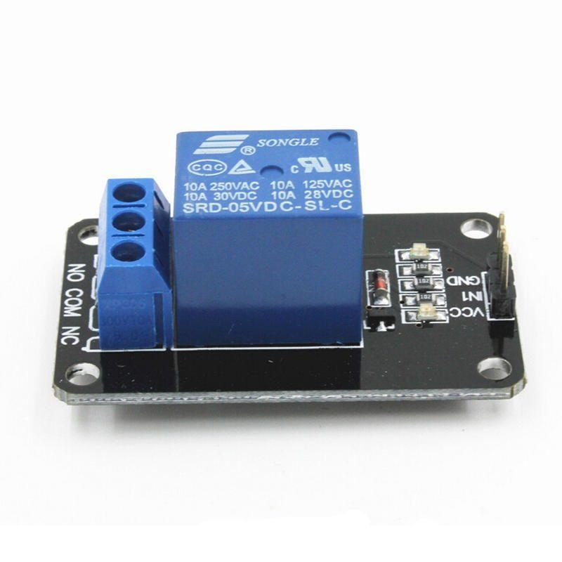
To explain the circuit. The fan is operated by 12V, that is, why there is 12V power source, 12V terminals and ground terminals for 12V circuits. I also did not want to have 12V on the fan all the time even when it is off, so I added a relay that will switch the power for the fan only when its needed. This is the standard single channel 5V relay that comes with most Arduino sets. That is, what the 5V power source terminals and terminals for 5V circuits are there for. The team up with respective terminals on the relay. A control terminal of the relay is connected to Arduino via orange cable on PIN 12. The plus terminal of the fan is connected to the 12V terminal block. The COM terminal of the relay (the middle one) is connected to the ground terminal block for 12V circuits. The minus (ground) terminal of the fan is connected to the NO terminal of the relay, closing the powering circuit of the fan. The PWM signal of the fan (blue wire) is connected to Arduino PWM PIN 9. Through this connection Arduino will control the speed of the fan. The RPM sensing terminal (green wire) is to PIN 2 via 1kΩ resistor in series.
And why is there the 1kΩ resistor? Well this comes from Noctua specifications, which says:
“All Noctua fans provide a tachometer output signal of the following characteristics: two cycles per revolution, open collector output. Maximum current is 5 mA for 5 V and 12 V fans and 2 mA for 24 V fans, so for example, when using a 12 V fan a resistor value of 2.7 kΩ or larger is suitable.”
Combined with the fact the input is defined as INPUT_PULLUP in the source code for the “enclosure firmware” – so it also uses the Arduino internal pullup resistor, I somehow came to the conclusion (when implementing it), that I can use 1kΩ resistor to be sure to stay within limitations of Noctua and Arduino. And also, this was one of the values of resistors I had in my set of stuff for Arduino at the time.
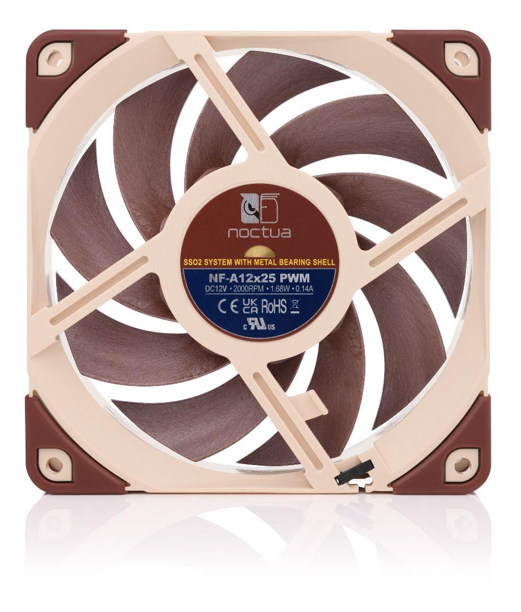
Below is the gallery of some of the used components:

Ventilation Fan Doors
The ventilation fan output is covered by “doors”, which can be opened / closed based on our needs. It would be a little silly to build an enclosure to capture temperature for printing and letting it escape through giant hole for the fan in the ceiling. The doors are controller through micro servo – again the basic component that comes with most Arduino sets.
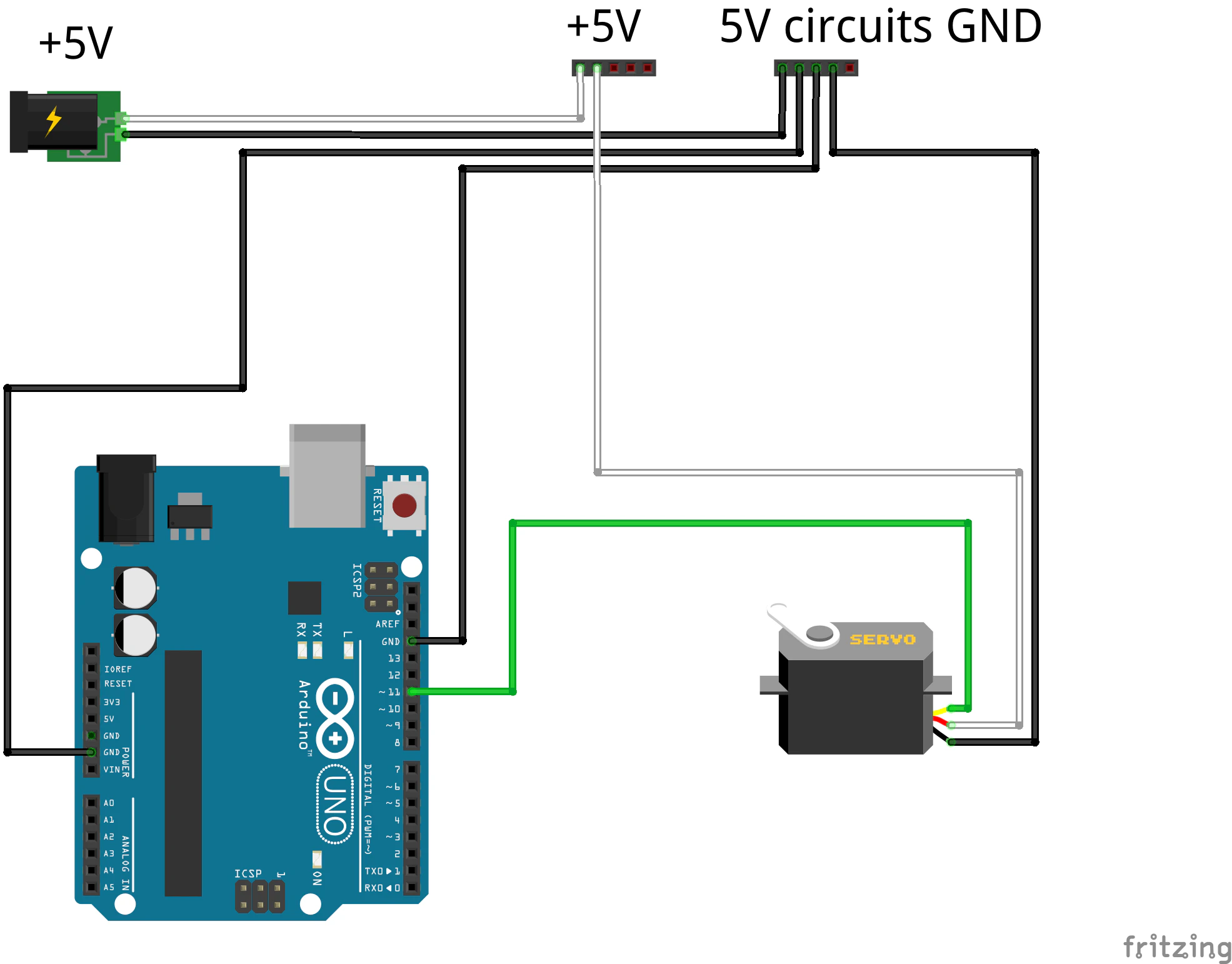
Here the wiring is like pasted from Arduino tutorials. Nothing special. The plus (Vcc) terminal of the servo goes to 5V terminal block. The minus (ground) connects to the ground terminal block for 5V circuits. And the last, control terminal, connects to PWM PIN 11 of Arduino via green cable.
The only tricky part in the wiring for me was identifying the right cables on the servo itself, as it comes with absolutely no description. By trial and error (and burning out 1 or 2) a find out that in the case of my servos – Vcc is the middle red cable, ground is the brown one and signal is the yellow one. Wish you luck with yours.
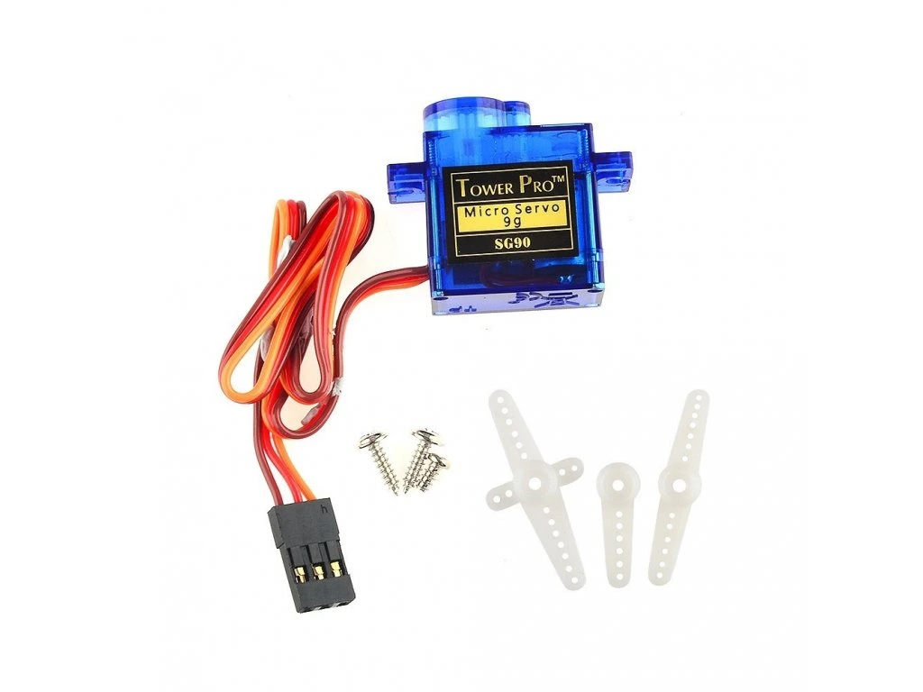
Below is the gallery of some of the used components:

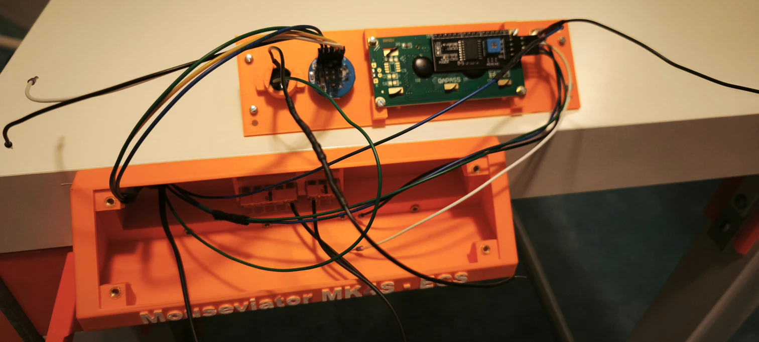
Control Panel
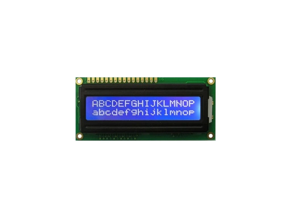
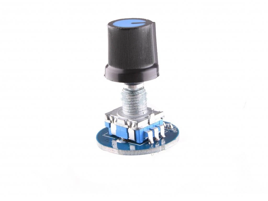
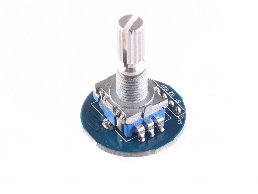
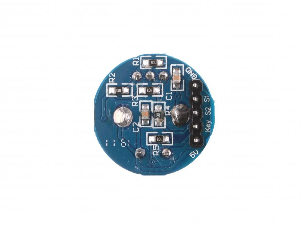
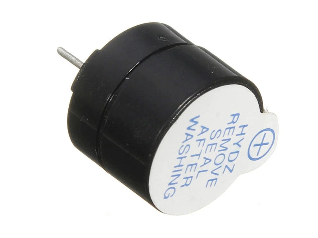
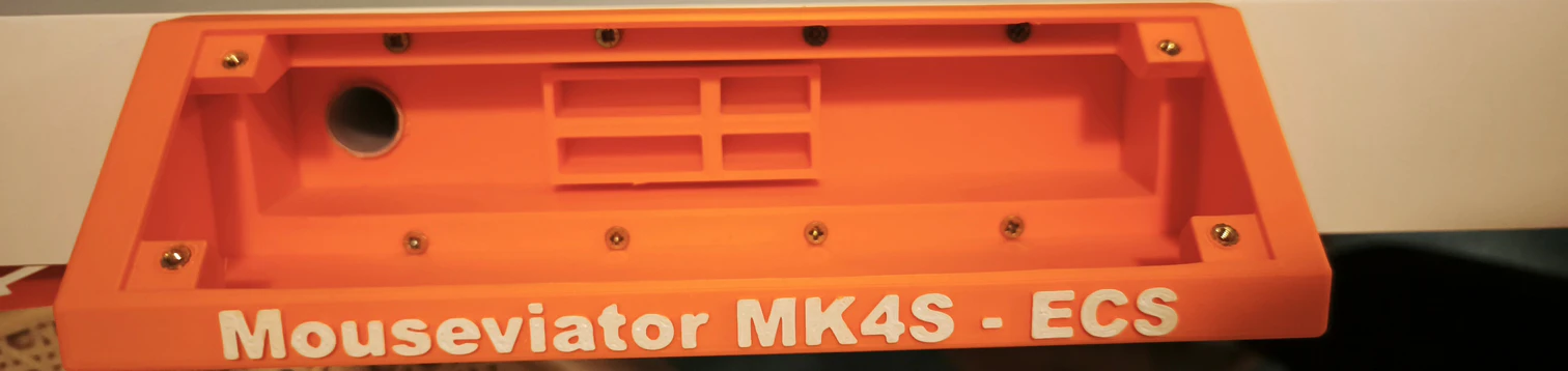
The control panel is the place where we will be communicating with “the machine”. Or the “Mouseviator MK4S – ECS” as I wrote on my control panel 🙂 Which stands for Mouseviator MK4S – Enclosure Control System 🙂 It consists of 16×2 LCD display, a rotatory encoder with a button, 5V active buzzer to make annoying sounds and a fancy red LED diode.
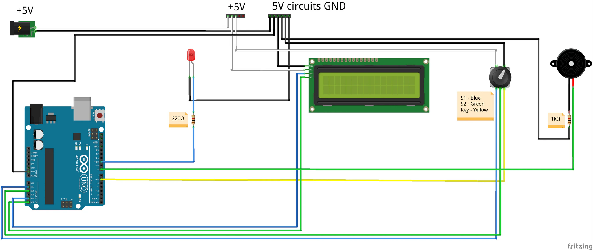
You can see that all of the components needs 5V to live. The 5V terminal block as well terminal block for 5V grounds are actually located inside the control panel housing and connected to the respective terminal blocks that are depicted on the “power box” diagram. I used “thicker than other Arduino connections” cable, I think its CYSY 2×0.75.
It might seem complicated, but it is mostly just the sum of connecting respective components by Arduino tutorials. The red LED is standard from the tutorials, with cathode to the ground and anode to Arduino output – PIN 10 via blue cable and 220Ω resistor in series.
The active buzzer is controlled through its positive terminal connected with Arduino via green cable on PIN 8. It’s ground is connected to … ground via 1kΩ pull-down resistor to prevent any unwanted or malicious behavior.
Despite the fact that the encoder utilizes 5 wires, it is also simple. As another components, it needs power, which leaves out 2 of those 5 wires for 5V Vcc (white one) and ground (black). Than it sends out two analog signals. S1 is connected via blue wire with analog PIN A1 on Arduino UNO. S2 is connected via green wire with analog PIN A2 on Arduino UNO. The last wire, yellow one is connected to PIN 6 and it is used to detect button press. We use encoder with RC filter which filters out noise and other nasty stuff that we would have to otherwise handle by software, making it more simple to use.
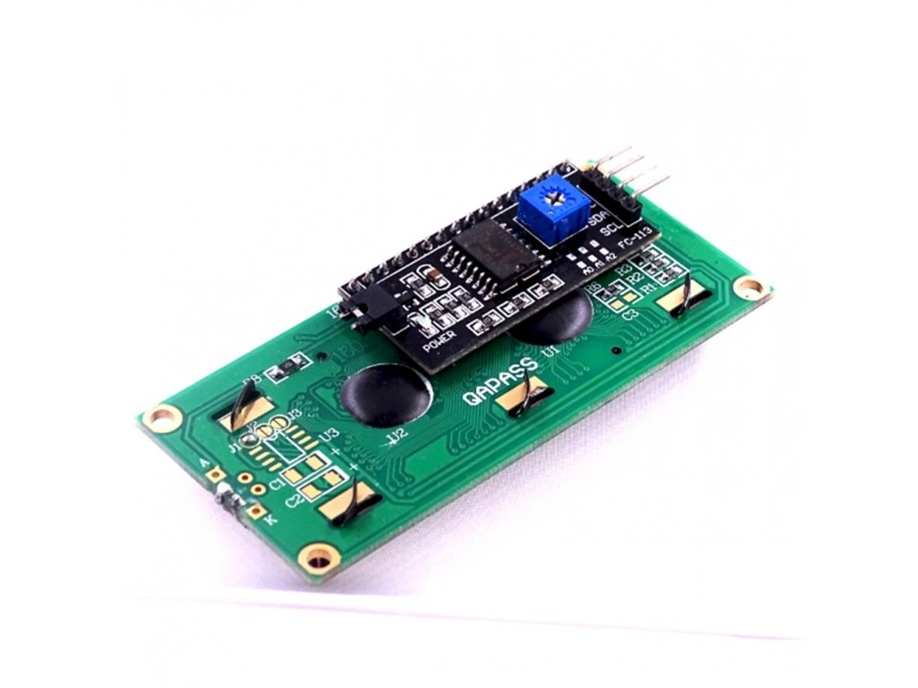
The last item left is the 16×2 LCD display with I2C encoder. It is also connected according to tutorials for this item and Arduino UNO. It needs power – so white one goes for Vcc and black for ground. Remaining terminals are SDA and SCL. SDA is connected via blue wire on analog PIN A4. SCL via green wire on analog PIN A5.
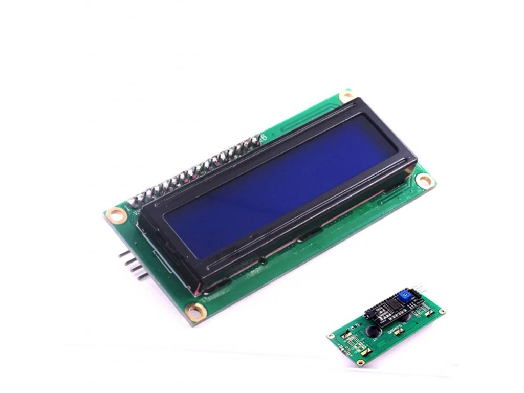
Below is the gallery of some of the used components:
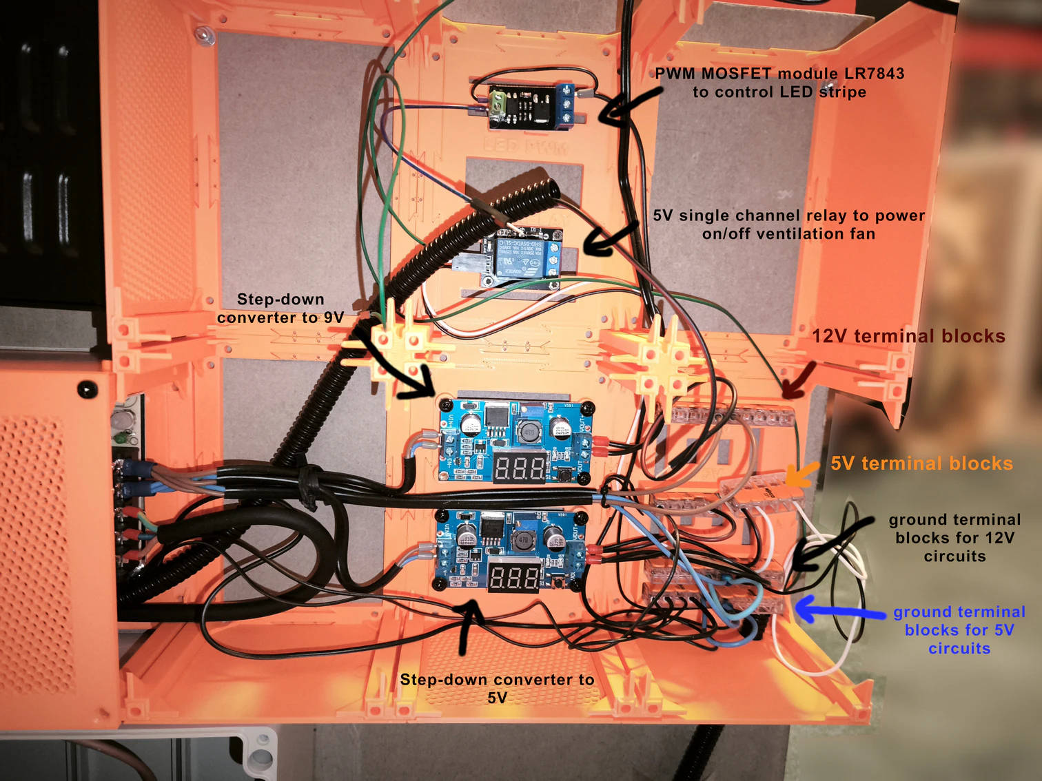
The wiring gallery
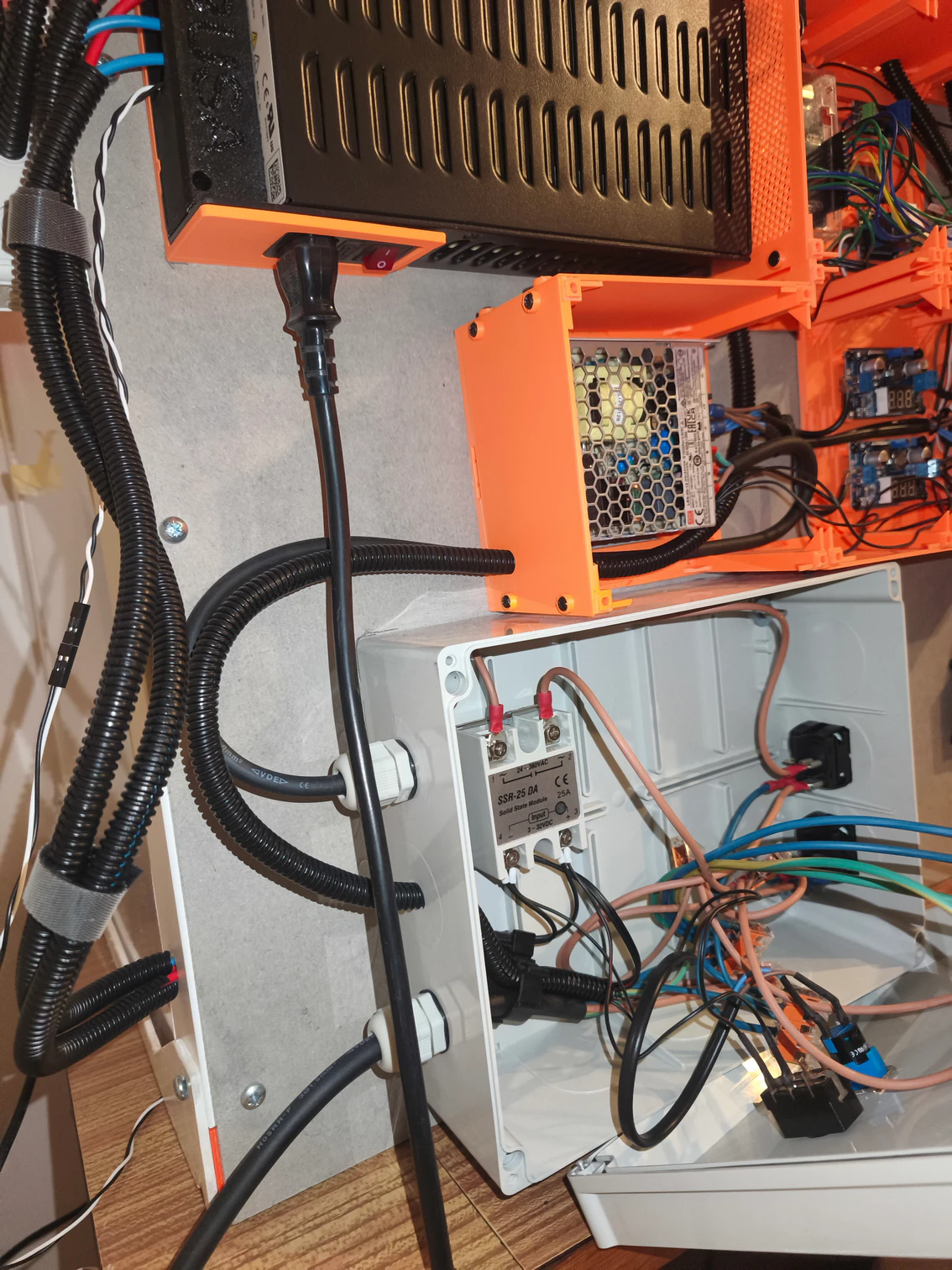
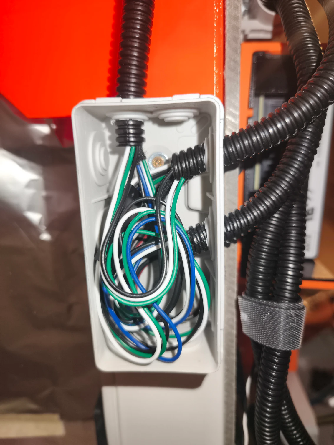
Below is the gallery with photos of actual, real world wiring:


That’s all folks
… don’t worry, just for today. Another episode is in writing. In the next one, we’ll start with Arduino programming. But I can’t promise when I publish it. I am again putting this together like “half a year” back. But, I needed to test it for a little while. And yet there are still some bugs and it’s not finally polished (who knows if it will ever be). But maybe you will help me.
And to remind:
You should not attempt to wire whats described here, unless you know what you are doing! If you are not sure, rather let some specialists do it. Be safe!!!
Links
In this section, I think links to used parts will fit well. First of all, parts used in the “power box” and the brain of the enclosure control:
- Arduino UNO Rev3
- Switching power supply – MEAN WELL LRS-50-12
- Step-down converter with LM2596 with LED display
- Compass PG-500 UPS
- FQFER SSR-xxDA Solid State Relay SSR 25-DA
- PWM MOSFET module LR7843, 30VDC 161A
- 1-channel 5V relay module, Low level, 250VAC 10A
Parts used for outside temperature and humidity sensor:
Parts used for inside temperature and humidity sensor:
Parts used for gase sensor:
Parts used for Ventilation fan:
Parts used to control Ventilation fan doors:
Parts used in Control panel:
- 16×2 LCD display 1602 blue + I2C converter
- Rotary encoder with button and RC filter
- Active buzzer 5V
All episodes of the series:
- The Tale of Building an enclosure for Prusa MK4S – The Idea
- The Tale of Building an enclosure for Prusa MK4S – Printed parts
- The Tale of Building an enclosure for Prusa MK4S – Wiring – this one 🙂
- The Tale of Building an enclosure for Prusa MK4S – Programming